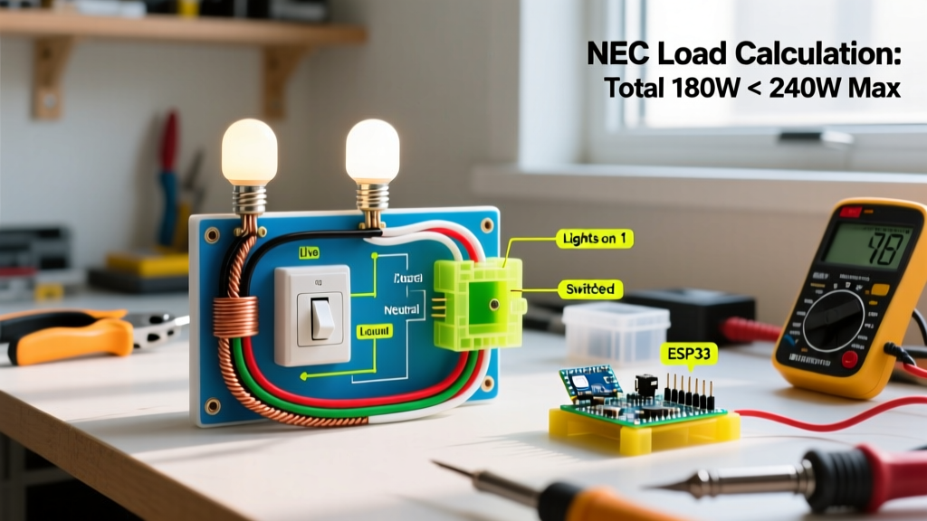

Strategic Planning for Multi-Fixture Lighting Circuits
Planning a multi-fixture lighting circuit requires far more than simply connecting black to black and white to white. When searching for a reliable wiring diagram for 2 lights on 1 switch, most DIYers and junior electricians miss the critical pre-installation calculations that ensure National Electrical Code (NEC) compliance, prevent voltage drop, and guarantee long-term thermal safety. This installation planning guide moves beyond basic schematic drawings, providing the exact material specifications, box-fill mathematics, and termination protocols required for a flawless 2026-compliant rough-in and trim-out.
Whether you are wiring a pair of exterior soffit lights or a dual-vanity bathroom setup, the topology we will cover is the Line-to-Switch-to-Fixture Daisy Chain. This specific layout is mandated by modern code updates to ensure a neutral conductor is always present at the switch box, future-proofing your circuit for smart home integrations.
NEC Compliance: Box Fill and Conductor Sizing
Before cutting a single piece of drywall or pulling wire, you must calculate the required junction box volume. Undersized boxes trap heat and make wire nut splices dangerously tight, leading to insulation degradation over time. We follow NFPA 70 National Electrical Code Article 314.16 for box fill calculations.
Switch Box Volume Calculation (15A Circuit)
Assume we are using 14 AWG copper conductors on a 15-Amp breaker. The switch box will receive power from the panel and send a switched leg to the first light.
- Current-Carrying Conductors: 2 from the panel (Line Hot, Line Neutral) + 2 to Light 1 (Switched Hot, Neutral) = 4 wires.
- Grounding Conductors: All bare/green grounds entering the box count as 1 wire equivalent.
- Device Yoke: The single-pole switch counts as 2 wire equivalents.
- Total Wire Equivalents: 4 + 1 + 2 = 7 equivalents.
Per NEC Table 314.16(B), each 14 AWG conductor requires 2.0 cubic inches of space. Therefore, 7 equivalents × 2.0 cu in = 14.0 cubic inches minimum. To allow ample room for modern push-in wire connectors and smart switch bodies, we specify a 22.5 cubic inch 'Super Blue' nail-on box (e.g., Carlon B122R) for the switch location.
Code Alert (NEC 300.14): You must leave at least 6 inches of unbroken conductor extending past the face of the box, and a minimum of 8 inches of total wire length inside the box. Measure and strip accordingly.
Material & Tool Matrix for 2026 Installations
Using contractor-grade materials prevents premature mechanical failure and arcing. Below is the precise bill of materials (BOM) for a standard 15-Amp residential lighting branch circuit.
| Category | Brand / Model | Specification | Est. Unit Cost |
|---|---|---|---|
| Branch Wire | Southwire SIMpull | 14/2 NM-B (Romex), 600V, Copper | $0.45 / ft |
| Switch Device | Leviton Decora 5601 | 15A Single-Pole, AC Quiet Toggle | $4.85 |
| Switch Box | Carlon B122R | 1-Gang, 22.5 cu in, PVC Nail-On | $2.10 |
| Light Boxes | Carlon CF1250R | 4-inch Round, 21 cu in, Old-Work | $3.40 |
| Wire Connectors | 3M Performance Plus | Wirelok W-548 (Red) / W-532 (Yellow) | $0.15 / ea |
| Stripping Tool | Klein Tools 11048 | Wire Stripper/Cutter for 14-10 AWG | $28.00 |
Note: If your home's branch circuit is protected by a 20-Amp breaker, you must upgrade all wiring to 12/2 NM-B and use a 20-Amp rated switch (e.g., Leviton 5602), per NEC 210.21.
Topology: The Wiring Diagram Logic
The most robust and code-compliant wiring diagram for 2 lights on 1 switch routes the main power feed directly to the switch box first. This guarantees the presence of a neutral wire at the switch, satisfying NEC Article 404.2(C), which is critical if you ever upgrade to Wi-Fi or Zigbee smart switches that require standby power.
Node 1: The Switch Box (Power Origin)
- Neutrals (White): Connect the white neutral wire from the panel feed directly to the white neutral wire heading to Light 1 using a red wire connector. Do not attach the neutral to the standard single-pole switch.
- Hots (Black): Connect the black hot wire from the panel to the bottom brass terminal of the switch. Connect the black wire heading to Light 1 to the top brass terminal of the switch.
- Grounds (Bare): Pigtail all bare copper grounds together with a green wire nut, and attach a 6-inch pigtail to the green grounding screw on the switch yoke.
Node 2: Light Fixture 1 (Intermediate Junction)
- Incoming Power: The 14/2 cable from the switch box enters the fixture canopy. The black wire is now a Switched Hot (it only carries 120V when the switch is ON).
- Outgoing Power: A second 14/2 cable leaves this box to feed Light 2.
- Splicing: Connect the incoming Switched Hot (Black), the outgoing Hot to Light 2 (Black), and the fixture's Black lead together. Connect all three White neutrals together. Connect all grounds together.
Node 3: Light Fixture 2 (End of Run)
- This box receives only one 14/2 cable from Light 1.
- Connect the incoming Black to the fixture Black. Connect the incoming White to the fixture White. Bond the incoming bare ground to the fixture ground and the metal box (if applicable).
Execution Protocol: Termination and Torque
The leading cause of residential electrical fires is loose terminal connections, which increase electrical resistance and generate localized heat. According to OSHA Electrical Safety Standards and manufacturer specifications, proper termination technique is non-negotiable.
Wire Preparation Standards
- Strip Length: Use the gauge on the back of the Leviton switch. For side-wiring (hooking the wire around the screw), strip exactly 3/4 inch of insulation. For back-wiring (inserting straight into the clamp), strip 5/8 inch.
- The Hook Method: When side-wiring, always loop the wire clockwise around the terminal screw. This ensures that tightening the screw pulls the wire loop tighter, rather than pushing it out from under the screw head.
- Torque Specification: Leviton specifies a terminal screw torque of 12 to 14 inch-pounds. Use a calibrated VDE-insulated torque screwdriver (e.g., Wiha 285T) to prevent stripping the soft brass threads or cracking the switch housing.
Edge Cases and Advanced Troubleshooting
Even with a perfect wiring diagram for 2 lights on 1 switch, real-world variables can introduce anomalies. Here is how to handle common edge cases during the commissioning phase.
LED Ghosting and Phantom Voltage
If you install highly sensitive LED bulbs (especially those under 5 Watts), you may notice a faint glow or 'ghosting' when the switch is in the OFF position. This occurs due to capacitive coupling between the parallel conductors in the 14/2 NM-B cable over long runs. Solution: Install a 100k-ohm, 1/2-watt bleeder resistor in parallel at the first light fixture, or upgrade to a switch with a built-in snubber circuit.
Voltage Drop on Extended Runs
If the total wire run from the breaker panel to Light 2 exceeds 75 feet, you risk exceeding the NEC recommended 3% voltage drop for lighting branch circuits. At 120V, a 3% drop means the voltage at Light 2 should not fall below 116.4V. Solution: Upsize the entire circuit run to 12/2 NM-B copper, even if protected by a 15-Amp breaker. The thicker 12 AWG wire reduces resistance and mitigates voltage drop over distance.
Smart Switch Integration
Because we utilized the Line-to-Switch topology, upgrading to a smart switch (like the Lutron Caseta PD-5S-DV) in the future is seamless. The neutral wire is already capped in the back of the switch box. Simply connect the smart switch's blue neutral wire to the existing bundle, eliminating the need to fish new 14/3 cable through finished walls.
Final Inspection & Energization Protocol
Before applying power, conduct a rigorous visual and mechanical inspection. Gently tug on every wire nut connection to ensure the conductors are fully seated and the spring steel inside the connector has bitten into the copper. Verify that no bare ground wires are touching the brass hot terminals on the switch—a classic fault that will cause an immediate dead short and trip the breaker violently.
Once the devices are secured in the boxes and the faceplates are installed, clear the area of all personnel. Stand to the side of the panel (never directly in front of it) and flip the 15-Amp breaker to the ON position. Test the switch operation. If the breaker holds and both fixtures illuminate simultaneously without flickering, your installation is complete, safe, and fully compliant with modern electrical standards. For further reading on energy-efficient lighting loads, consult the U.S. Department of Energy Lighting Guidelines to ensure your chosen LED fixtures maximize circuit efficiency.