
The Hidden Dangers of Unverified PDF Schematics
Searching for an electric scooter wiring diagram pdf free download usually indicates you are attempting to repair a blown motor controller, upgrade a lithium-ion battery pack, or troubleshoot a dead throttle. While the internet is flooded with user-uploaded schematics on forums and file-sharing sites, relying on these unverified documents poses a severe safety and code compliance risk. In 2026, with micromobility fire incidents prompting strict local and federal regulations, understanding the electrical architecture of your scooter is no longer just about making it run—it is about preventing catastrophic thermal runaway.
Generic wiring diagrams often fail to account for specific manufacturer revisions, Battery Management System (BMS) protocols, and localized fire codes. A mismatched pinout or an undersized wire gauge recommendation in a random PDF can lead to short circuits, MOSFET blowouts, and lithium-ion battery fires. This guide provides the technical depth required to evaluate, verify, and safely implement wiring diagrams while adhering to modern electrical safety standards.
Critical Safety Standards for E-Scooter Wiring (2026 Update)
Before executing any wiring repair based on a downloaded schematic, you must understand the regulatory framework governing light electric vehicles (LEVs). Modifying an e-scooter using non-compliant diagrams immediately voids its safety certification and may violate local fire codes.
- UL 2849 (Electrical Systems for e-Bikes and e-Scooters): This standard evaluates the entire electrical drivetrain, including the motor, controller, wiring harness, and battery charger. A compliant wiring diagram must show integrated thermal fuses and proper strain relief on all harness connections.
- UL 2271 (Light Electric Vehicle Batteries): Focuses specifically on the battery pack and BMS. Safe diagrams will explicitly detail the BMS balancing wire routing and the separation of charge and discharge circuits.
- Local Fire Codes (e.g., NYC Local Law 39): Following a surge in e-mobility fires, jurisdictions like New York City now mandate that all e-scooters and their electrical components meet UL certification. The FDNY Lithium-Ion Battery Safety Guidelines explicitly warn against using modified or uncertified electrical components, which are often the result of following forum-sourced wiring PDFs.
⚠️ Compliance Warning: According to the CPSC Micromobility Technical Reports, aftermarket wiring modifications that bypass factory thermal protection or utilize non-OEM harnesses are a leading cause of micromobility product recalls and fire investigations.
Decoding a Code-Compliant Electric Scooter Wiring Diagram
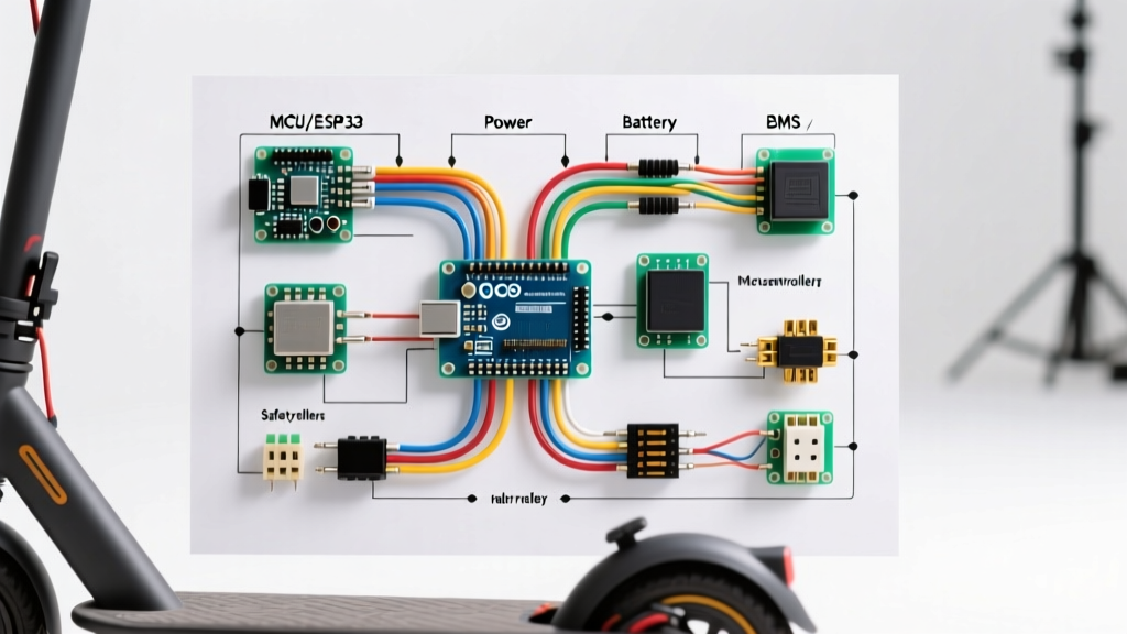
A legitimate, OEM-level wiring diagram contains specific safety architectures that generic PDFs frequently omit. When reviewing your downloaded schematic, verify the presence of the following critical circuits:
1. BMS Discharge vs. Charge Routing
The most fatal error found in free PDF downloads is the misidentification of BMS pads. A standard 13S 48V BMS features three main negative pads: B- (Battery Negative), C- (Charge Negative), and P- (Pack/Discharge Negative). The motor controller's main negative wire must connect to P-. Many incorrect diagrams instruct users to connect the controller to C- or directly to B-, which completely bypasses the BMS discharge overcurrent and short-circuit protection, creating a direct path for thermal runaway during heavy acceleration.
2. Brake Cutoff Logic (Fail-Safe Integration)
Code-compliant diagrams integrate electronic brake cutoffs. You must verify whether the diagram specifies Active-Low (pulling the signal wire to ground to trigger the cutoff) or Active-High (pulling the signal to 5V). Connecting an Active-High brake switch to an Active-Low controller input will instantly short the controller's 5V LDO voltage regulator, permanently destroying the logic board and potentially leaving the motor stuck in a wide-open throttle state.
3. Wire Gauge and Connector Specifications
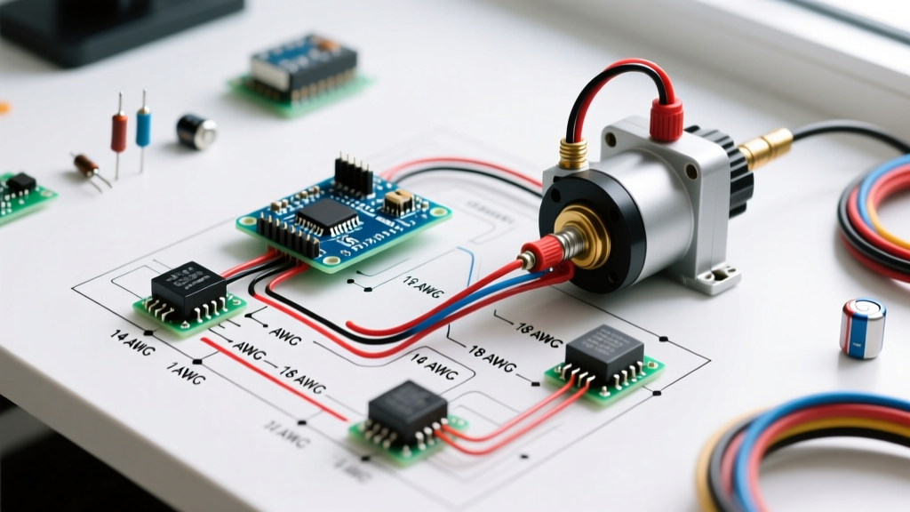
Safe diagrams specify exact American Wire Gauge (AWG) ratings and connector types based on continuous and peak amperage. Using the XT60 connector for a 40A continuous system is a fire hazard; the UL e-Mobility Safety Standards require connectors rated for at least 125% of the continuous system draw.
| Circuit Application | Recommended Wire Gauge (AWG) | Max Continuous Current | Required Connector Type |
|---|---|---|---|
| Battery to Controller (Main Power) | 8 AWG Silicone | 70A | XT90 or QS8 (Anti-Spark) |
| Controller to Motor (Phase Wires) | 10 AWG or 12 AWG | 50A - 80A Peak | Bullet Connectors (5.5mm) with Heat Shrink |
| Throttle & Hall Sensors (Signal) | 22 AWG to 24 AWG | < 1A | JST-SM or HIGO (Waterproof) |
| BMS Balancing Ribbons | 18 AWG Stranded | 2A (Balancing only) | JST-XH (2.54mm pitch) |
Step-by-Step: Verifying Your Downloaded Diagram Against Code
Do not solder a single wire until you have run your downloaded PDF through this verification matrix:
- Verify the Battery Chemistry and Series Count (S): A 48V system is typically 13S (54.6V fully charged). A 52V system is 14S (58.8V fully charged). If your PDF is for a 48V system but you are using a 52V battery, the controller's capacitors (usually rated for 63V) will be operating dangerously close to their breakdown voltage. Always match the diagram's series count to your physical cell layout.
- Check Hall Sensor Voltage: Most modern scooter motors use 5V Hall effect sensors for rotor position. Some older or heavy-duty diagrams route 12V to the Hall power line. Sending 12V into a 5V sensor will instantly fry the sensor array inside the motor hub.
- Inspect the Anti-Spark Circuit: High-amperage e-scooters (30A+) require an anti-spark resistor or pre-charge circuit in the main power loop. If your free PDF lacks this, plugging in the battery will cause a massive inrush current that will pit and degrade your XT90 connectors and weld the controller MOSFETs shut.
- Confirm IP Ratings on Harnesses: For outdoor compliance, signal connectors must be waterproof. Generic diagrams often specify standard JST-SM connectors for throttles and displays. In wet conditions, these wick moisture directly into the controller via capillary action. Upgrade to HIGO or IP67-rated JST connectors as specified in OEM service manuals.
Common Failure Modes from Incorrect PDF Schematics
When electrical engineers reverse-engineer burnt e-scooter controllers, they frequently find damage patterns directly traceable to incorrect wiring diagrams:
- Phase Wire Shorting: Generic diagrams often fail to specify the necessity of high-temperature silicone jacketing for phase wires. Standard PVC insulation melts against the hot motor stator, causing a phase-to-phase short that instantly destroys the controller's power stage.
- Missing Flyback Diodes: If your schematic involves wiring auxiliary relays or solenoids for lighting or locking mechanisms, it must include flyback diodes. Without them, the inductive kickback from the relay coil will send a high-voltage spike back into the controller's 5V logic rail.
- Shared Ground Loops: Improper PDFs often daisy-chain the ground wires for the high-current motor hall sensors and the low-current LCD display. This creates a ground loop where motor noise induces voltage spikes in the display, causing system reboots and erratic throttle readings.
Where to Legally Source OEM & Code-Compliant Wiring Schematics
Rather than risking a fire hazard with a random electric scooter wiring diagram pdf free download from an unverified message board, utilize these authoritative sourcing methods:
- Manufacturer Service Portals: Brands like Segway-Ninebot, Apollo, and Voro Motors provide official service manuals and wiring matrices to registered owners and certified repair shops. These documents include exact pinout revisions and torque specifications for terminal blocks.
- Controller Manufacturer Datasheets: If you are replacing a controller, download the official datasheet from the manufacturer (e.g., Kelly Controllers, Sabvoton, or VESC-based hardware providers). These datasheets provide mathematically verified wiring schematics tailored to the specific firmware flashed on your unit.
- Certified LEV Repair Networks: Consult with UL-certified micromobility repair centers. They possess proprietary diagnostic software and OEM wiring harness schematics that guarantee your repair meets current fire and safety codes.
Conclusion: Prioritize Safety Over Convenience
While the search for an electric scooter wiring diagram PDF free download is driven by the desire for quick, cost-effective repairs, the electrical complexity of modern lithium-ion micromobility devices demands rigorous attention to safety and code compliance. By understanding BMS routing, verifying brake cutoff logic, adhering to proper AWG wire gauges, and respecting UL standards, you ensure that your e-scooter remains a safe, reliable mode of transport rather than a severe fire hazard. Always cross-reference any downloaded schematic against official OEM documentation and current electrical safety guidelines before applying power to your system.