
Mastering the Wiring Diagram for Furnace Blower Motor Diagnostics
When a forced-air heating system fails to circulate warm air, the blower motor assembly is often the first suspect. However, blindly replacing components is an expensive guessing game. By systematically interpreting the wiring diagram for furnace blower motor circuits, technicians and advanced DIYers can isolate the exact point of failure—whether it is a faulty Integrated Furnace Control (IFC) board, a degraded run capacitor, or a shorted motor winding. This guide breaks down the schematic tracing process for both legacy Permanent Split Capacitor (PSC) motors and modern Electronically Commutated Motors (ECM), providing actionable multimeter testing protocols and 2026 market pricing.
CRITICAL SAFETY WARNING: Before removing any access panels or touching electrical terminals, you must disconnect the main power supply at the breaker panel and utilize Lockout/Tagout (LOTO) procedures. According to OSHA's hazardous energy control standards, failing to isolate 120V and 240V circuits can result in fatal arc flashes or electrocution. Always verify zero voltage with a CAT III or CAT IV multimeter before proceeding.
Decoding PSC Motor Color Codes and Terminals
Older or standard-efficiency furnaces typically utilize PSC blower motors. The wiring diagram for these units relies on a standardized color-coded harness that dictates the motor's speed taps. Understanding these colors is the first step in schematic troubleshooting:
- Black (High Speed): Typically wired to the COOL terminal on the IFC board. Used for air conditioning to overcome the higher static pressure of the evaporator coil.
- Blue (Medium Speed): Often used for continuous fan circulation or intermediate heating stages.
- Red (Low Speed): Wired to the HEAT terminal on the IFC board. Lower speed prevents drafts during the heating cycle.
- White (Neutral/Common): Connects directly to the neutral bus or the common side of the 120V transformer.
- Brown & Brown/White (Capacitor): These wires do not route to the control board. They connect exclusively to the run capacitor (usually rated between 5 MFD and 15 MFD at 370V/440V).
Tracing the PSC Power Path
When tracing the diagram, note that the neutral (White) provides a continuous path to the motor windings. The 120V 'Hot' leg routes from the main power supply, through the IFC board's internal relay or triac, and out to the specific speed tap (e.g., Black or Red). If the motor is humming but not spinning, use your wiring diagram to locate the capacitor terminals. A swollen or leaking capacitor is the culprit in over 60% of PSC motor failures.
PSC vs. ECM: Identifying Your Blower Architecture
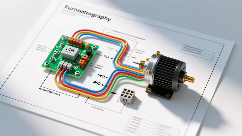
Modern high-efficiency furnaces (90%+ AFUE) mandate the use of ECM technology to meet Department of Energy and ENERGY STAR HVAC efficiency guidelines. Troubleshooting an ECM requires a completely different approach than a PSC motor, as the schematic will show a complex low-voltage control harness rather than simple 120V line voltage taps.
| Feature | PSC (Permanent Split Capacitor) | ECM (Electronically Commutated) |
|---|---|---|
| Wiring Complexity | Low (4-5 main wires + capacitor) | High (16-pin control harness + 5-pin power) |
| Speed Control | Fixed taps (High, Med, Low) | Infinite variable speed via microprocessor |
| Troubleshooting Method | Ohm testing windings, capacitor testing | Checking 24V AC logic signals, thermistor checks |
| Common Failure Point | Run capacitor, worn bearings | ECM control module (thermistor/relay failure) |
| 2026 Avg. Replacement Cost | $140 - $250 (Motor only) | $350 - $600 (Module) / $900 - $1,400 (Full) |
Tracing the 16-Pin ECM Harness: A Schematic Deep Dive
If your wiring diagram for the furnace blower motor depicts a 16-pin Molex connector, you are dealing with an ECM (such as the ubiquitous Genteq 3.0 or Century Centurion series). The IFC board does not send 120V to dictate speed; instead, it sends 24V AC logic signals to the motor's internal microprocessor. Here is how to trace the critical pins:
- Pins 1 & 2 (24V AC Power): Pin 1 is the 24V Hot (R), and Pin 2 is the 24V Common (C). If the motor module has no LEDs illuminated, test between these two pins. If you lack 24V AC, the fault lies in the IFC board's transformer or a blown 3-amp automotive fuse on the board.
- Pins 3, 4, & 5 (Speed Commands): These pins correspond to Low Heat, High Heat, and Cooling. When the thermostat calls for heat, the IFC board energizes Pin 3 or 4 with 24V AC. If you measure 24V at Pin 4 (High Heat) but the blower remains off, the ECM module is defective.
- Pins 9 & 10 (Comfort Profiles): Many diagrams show jumper plugs between these pins to configure the motor's ramp-up profile and tonnage (e.g., 2.5-ton vs. 5-ton cooling). Missing or corroated jumpers will cause the motor to default to a failsafe low-speed mode.
Multimeter Diagnostic Matrix for Blower Circuits
Use the following matrix in conjunction with your specific unit's wiring diagram to systematically eliminate variables. Ensure your multimeter is set to the correct function before probing.
| Test Point (per Diagram) | Multimeter Setting | Expected Value | Fault Indication |
|---|---|---|---|
| IFC Board HEAT to Neutral | AC Volts | ~120V AC | 0V = Failed board relay/triac. 120V = Motor issue. |
| Motor Common to Start (PSC) | Ohms (Ω) | 3 - 15 Ω | OL (Open) = Blown internal winding or tripped thermal limit. |
| Motor Common to Run (PSC) | Ohms (Ω) | 10 - 25 Ω | OL = Open winding. Short to ground = Motor replacement required. |
| ECM 16-Pin Harness (Pin 1 to 2) | AC Volts | 24V AC | 0V = Blown 3A fuse on IFC or bad transformer. |
| Run Capacitor Terminals | Microfarads (MFD) | Within 6% of rating | Reading below 10% of rating = Weak/failed capacitor. |
Direct-Wire Bench Testing: Bypassing the IFC Board
Sometimes the wiring diagram indicates multiple safety interlocks (like high-limit switches or pressure switches) wired in series with the blower relay. To determine if the motor itself is dead, you can perform a direct-wire bench test. Note: This should only be done by qualified individuals adhering to NFPA 70 (National Electrical Code) safety protocols.
For a PSC motor, disconnect the harness from the IFC board. Wire the White (Common) directly to the neutral terminal of a known-good 120V receptacle. Wire the Black (High Speed) directly to the 120V hot terminal. Ensure the Brown and Brown/White wires are securely connected to a properly rated run capacitor. If the motor spins up smoothly on the bench, the motor is functional, and the fault lies upstream in the furnace control board or safety interlocks.
2026 Market Insights: Repair vs. Replace Economics
As of 2026, the HVAC supply chain has largely stabilized, but the cost disparity between PSC and ECM components remains stark. A standard Fasco or Century PSC replacement motor costs between $140 and $250. However, if your wiring diagram reveals an ECM architecture, you face a critical decision. The ECM control module (the plastic housing attached to the back of the motor) can be replaced independently for $350 to $600. But if the internal stator or rotor bearings are seized, a complete ECM motor assembly from premium brands like Trane or Lennox will cost between $900 and $1,400. When tracing the diagram reveals a dead ECM module on a furnace older than 12 years, many technicians recommend upgrading the entire system rather than sinking $1,000 into an aging heat exchanger.
Final Schematic Verification
Always cross-reference the physical wire colors with the schematic printed on the inside of the furnace blower access door. Manufacturers frequently update harness designs mid-production run. Relying on memory rather than the specific wiring diagram for your furnace blower motor's exact serial number is the most common cause of misdiagnosis and secondary component damage.