
Mastering the John Deere Electric PTO Clutch Wiring Diagram
When the mower deck on your John Deere L130, X300, or commercial Z-Trak refuses to engage, the immediate suspicion often falls on the PTO (Power Take-Off) clutch itself. However, as any seasoned small engine electrician knows, the clutch is frequently the victim, not the culprit. The true source of the failure usually lies within the mower's electrical panel, switch harness, or relay configuration. Understanding the John Deere electric PTO clutch wiring diagram is essential for accurately diagnosing voltage drops, identifying burnt relays, and preventing catastrophic harness meltdowns.
From a panel and breaker perspective, the PTO circuit is a high-draw inductive load. When the electromagnet engages, it experiences a massive inrush current before settling into a steady state. If your wiring gauge is undersized, or if the inline breaker is fatigued, the clutch will slip, overheat, and eventually fail. This guide breaks down the exact circuit architecture, wire sizing requirements, and multimeter diagnostics needed to restore your John Deere's PTO system to factory specifications in 2026.
Anatomy of the JD PTO Panel Circuit
John Deere utilizes two primary PTO wiring architectures across its lawn and garden lineup. Identifying which one your tractor uses is the first step in reading the wiring diagram:
- Direct-Switch Configuration (L-Series & Older X-Series): Common on models like the L120 and L130. The ignition switch or a dedicated dash toggle routes 12V DC directly through a 10-amp or 15-amp inline fuse to the PTO clutch coil. This setup is notorious for burning out dash switches due to the 4-amp continuous load.
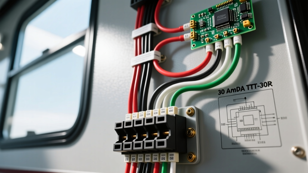
- Relay-Switch Configuration (X500 Series & Z-Trak Commercial): Used on higher-end models like the X570 and Z930M. A low-amperage dash switch triggers a 30-amp automotive relay located in the main distribution panel. The relay then routes heavy-gauge battery power directly to the clutch, bypassing the delicate dash wiring.
Wire Gauge, Breaker Sizing, and Routing
A common mistake in DIY PTO replacements is reusing the degraded, undersized factory wiring or pairing a new clutch with an inadequate inline fuse. According to SAE J1128 standards for low-tension primary cable, automotive wire must be sized not just for the continuous amperage, but for the voltage drop over the physical distance from the battery to the clutch.
A standard John Deere PTO clutch (such as the Warner Electric 5218-101-005 or the Xtreme Power XC3785-10) draws between 3.5A and 5.5A on initial engagement, settling at roughly 2.5A to 3.0A. While a 14 AWG wire might technically handle 3 amps, the physical distance on a zero-turn mower introduces resistance. If voltage at the clutch drops below 11.5V DC under load, the electromagnetic field weakens, causing the clutch to slip and draw more amperage, creating a thermal runaway loop.
Recommended Panel & Wire Sizing Matrix
| Tractor Class | Wire Gauge (Copper) | Inline Fuse / Breaker | Relay Requirement |
|---|---|---|---|
| Residential (L100-L200) | 12 AWG SAE | 15A ATO Blade Fuse | Highly Recommended (Retrofit) |
| Premium (X300-X500) | 12 AWG SAE | 20A Auto-Reset Breaker | Mandatory (Factory Panel) |
| Commercial (Z-Trak 900) | 10 AWG SAE | 30A ATO Blade Fuse | Mandatory (Heavy-Duty 40A Relay) |
Note: Always use marine-grade tinned copper wire for PTO routing, as the underside of a mower deck is exposed to extreme moisture, fertilizer chemicals, and vibration.
Step-by-Step Wiring Diagram Flow (Relay Configuration)
For modern John Deere tractors utilizing a relay panel, the circuit flows as follows. Use this sequence to trace faults with a multimeter:
- Power Source: Battery Positive (+) to the Main Panel Distribution Block.
- Circuit Protection: Distribution Block to a 20A or 30A Inline Fuse / Breaker.
- Relay Feed (Pin 30): Fused 12V+ connects directly to Pin 30 on the standard 4-pin ISO automotive relay.
- Switch Feed (Pin 86): A separate, smaller gauge (16 AWG) 12V+ wire runs from the ignition switch to the PTO dash switch, then to Relay Pin 86.
- Relay Ground (Pin 85): Relay Pin 85 grounds to the chassis.
- Clutch Feed (Pin 87): When the dash switch closes, the relay coil energizes, connecting Pin 30 to Pin 87. Heavy 12 AWG wire carries 12V+ from Pin 87 directly to the PTO Clutch Positive terminal.
- Clutch Ground: The PTO Clutch Negative terminal grounds directly to the engine block or main chassis ground lug.
Critical Warning: The John Deere Harness Diode
Many JD L-Series and X-Series models feature a small, black inline diode spliced into the PTO switch harness. This diode acts as a flyback suppressor and prevents alternator back-feed. When you turn the PTO off, the collapsing magnetic field in the clutch coil sends a massive voltage spike backward. Without this diode, the spike will instantly fry the tractor's voltage regulator/rectifier. Never remove or bypass this diode during a wiring repair. If replacing the harness, ensure the aftermarket kit includes the integrated suppression diode.
Multimeter Diagnostics & Resistance Benchmarks
Before tearing into the dash panel or replacing a $200 clutch, you must verify the electrical parameters. Set your digital multimeter to the following tests to isolate the failure point.
1. Static Coil Resistance Test (Ohms)
Disconnect the clutch wiring harness. Set your multimeter to Ohms (Ω) and touch the probes to the clutch terminals. A healthy John Deere / Warner Electric clutch should read between 2.2 and 3.8 Ohms. If you read infinite resistance (OL), the internal coil is broken. If you read below 1.5 Ohms, the coil has shorted internally and will immediately blow your panel fuse upon engagement.
2. Dynamic Voltage Drop Test (DC Volts)
Reconnect the harness, start the engine, and engage the PTO. Pierce the positive wire near the clutch connector with your multimeter probe. You must see a minimum of 11.8V DC. If your battery reads 13.2V at the terminals but only 10.5V reaches the clutch, you have severe resistance in the panel breaker, the relay contacts, or a corroded chassis ground.
3. The Mechanical Air Gap Factor
Electrical diagnostics are incomplete without checking the mechanical air gap. As the clutch friction surfaces wear, the gap widens. If the gap exceeds 0.035 inches, the electromagnet cannot pull the armature across the gap efficiently. The clutch will slip, causing amperage to spike and the wiring to melt. Use a feeler gauge to check the gap around the circumference of the clutch. If it exceeds 0.030", adjust the locknuts on the mounting bolts to bring the gap back to the factory 0.018" to 0.024" specification.
2026 Aftermarket Upgrades vs. OEM Replacements
When a PTO clutch fails, owners face a choice between OEM John Deere parts and aftermarket alternatives. As of 2026, OEM John Deere clutches (often rebranded Warner or Ogura units) typically retail between $350 and $480. Conversely, premium aftermarket options like the Xtreme Power Clutches series offer upgraded epoxy-potted coils and higher-temperature friction materials for $160 to $220.
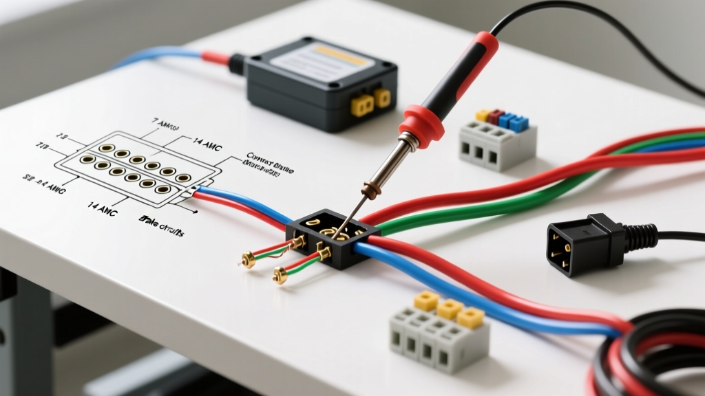
From a wiring perspective, aftermarket clutches sometimes feature slightly different terminal orientations (straight vs. 90-degree spades). When installing an aftermarket unit on an older JD panel harness, you may need to install new weather-pack sealed connectors and heat-shrink butt splices to prevent moisture intrusion, which is the leading cause of terminal corrosion and subsequent voltage drop.
Summary Checklist for PTO Panel Maintenance
- Inspect the main distribution panel for melted relay sockets; upgrade to a ceramic-base relay if operating in high-ambient heat.
- Verify the inline fuse holder is sealed; replace cracked plastic ATO holders with marine-grade rubberized versions.
- Clean the engine block ground lug where the clutch negative wire terminates; bare metal-to-metal contact is mandatory.
- Measure the clutch air gap annually and adjust to 0.020" to prevent electrical over-draw.
By treating the PTO system not just as a mechanical attachment, but as a critical, high-draw electrical circuit governed by strict panel and breaker rules, you can eliminate recurring clutch failures and ensure your John Deere mower operates reliably through the heaviest cutting seasons.