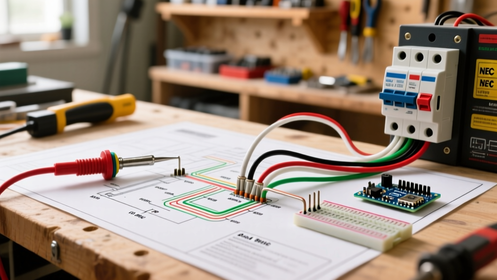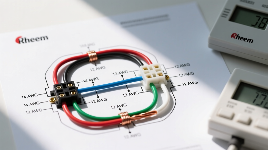

Understanding the Wiring Diagram for a Two Way Switch in Appliance Circuits
When designing a workshop, kitchen, or utility space, controlling a hardwired appliance from multiple entry points is a massive convenience and safety upgrade. Whether you are wiring a 1.5 HP workshop dust collector, a heavy-duty attic exhaust fan, or a hardwired commercial range hood, understanding the wiring diagram for a two way switch is critical. This guide bridges the gap between standard lighting tutorials and the rigorous demands of inductive appliance loads, ensuring your circuit meets modern electrical codes in 2026.
Crucial Terminology: Global Naming Conventions
Before cutting any wire, we must address a dangerous terminology trap that causes countless short circuits. The term 'two-way switch' means different things depending on your region:
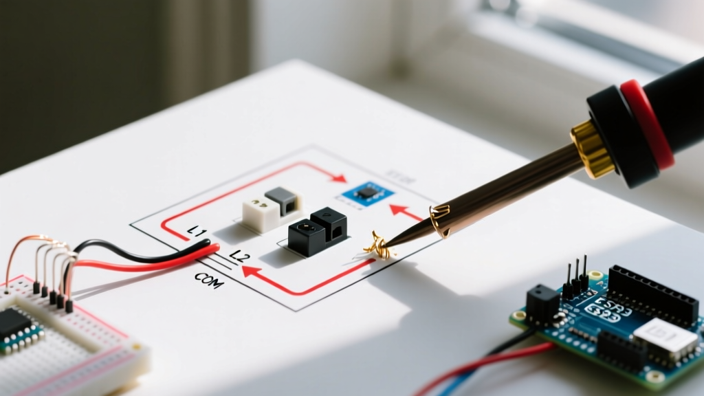
- UK / Australia / Europe (BS 7671 / AS/NZS 3000): A 'Two-Way Switch' allows you to control a single load from two different locations (e.g., top and bottom of a staircase). It features a Common (COM), L1, and L2 terminal.
- North America (NEC / CEC): The exact same functionality is called a 'Three-Way Switch'. It features a Common (dark screw) and two Traveler (brass screws) terminals. In the US, a 'two-way switch' actually refers to a standard single-pole on/off switch.
This tutorial focuses on the multi-location control circuit (UK 2-Way / US 3-Way), as this is the universal intent behind the search for a two-way appliance wiring diagram. We will provide specifications for both North American and UK/AU standards.
Appliance Load Calculations and Component Sizing
Unlike incandescent lighting, appliances with electric motors (like dust collectors or exhaust fans) present an inductive load. When a motor starts, it experiences Locked-Rotor Current (LRC), which can be 5 to 7 times higher than its running Full-Load Current (FLC). Standard residential 15A lighting switches will rapidly burn out their internal contacts when subjected to motor startup arcs.
Code Compliance Note: According to the National Fire Protection Association (NFPA 70 / NEC), switches controlling motor loads must be rated for the specific horsepower or have an ampacity rating sufficient to handle the inductive surge without pitting the contacts. Always check the manufacturer's FLA (Full Load Amps) on the appliance nameplate.
Materials Matrix: US vs. UK/AU Standards
| Component | North America (NEC 20A Circuit) | UK / AU (BS 7671 16A Circuit) |
|---|---|---|
| Switch Type | 20A Heavy-Duty 3-Way Toggle (e.g., Leviton 5605-2W) | 16A 2-Way Grid Switch (e.g., Schneider L5312) |
| Cable (Travelers) | 12/3 NM-B with Ground (Romex) | 1.5mm² 3-Core + Earth PVC |
| Cable (Line/Load) | 12/2 NM-B with Ground | 1.5mm² 2-Core + Earth PVC |
| Max Continuous Load | 16 Amps (80% rule for 20A breaker) | 12.8 Amps (80% rule for 16A MCB) |
| Terminal IDs | Common (Black), Travelers (Brass) | Common (COM), Strappers (L1, L2) |
Step-by-Step Wiring Diagram for a Two Way Switch (Appliance Load)
The following procedure outlines the 'Power to Switch 1, Travelers to Switch 2, Load to Appliance' topology. This is the most common and code-compliant layout for retrofitting an appliance circuit in an existing structure.
Phase 1: Power Source to Switch Box 1 (The Line)
- Kill the Power: Turn off the 20A (US) or 16A (UK) circuit breaker at the main distribution panel. Verify zero voltage with a non-contact voltage tester (NCVT) and a digital multimeter.
- Feed the Box: Run your 12/2 (or 2-core) supply cable from the panel into the first deep junction box (minimum 30 cubic inches to accommodate box fill requirements).
- Connect the Ground: Pigtail the bare/green-yellow earth wire to the green grounding screw on Switch 1 and to the metal box (if applicable) using a grounding clip.
- Neutral Bypass: Cap the white/blue neutral wire with a wire nut (Wago 221 lever connectors are highly recommended for 2026 best practices). Note: Standard mechanical two-way switches do not use a neutral. Smart switches, however, do. If using a smart relay, the neutral must be routed to the switch.
- Hot to Common: Connect the black/brown Line (Hot) wire to the Common terminal (the dark-colored or distinctly marked screw) on Switch 1.
Phase 2: Switch 1 to Switch 2 (The Travelers / Strappers)
- Run the 3-Core Cable: Pull your 12/3 NM-B (US) or 3-core + earth (UK) cable between Switch Box 1 and Switch Box 2.
- Ground Continuity: Splice the ground wires in both boxes to ensure continuous equipment grounding.
- Neutral Continuity: Pass the white (US) or blue (UK) neutral wire straight through both boxes using Wago connectors. This neutral will eventually terminate at the appliance to complete the 120V/230V circuit.
- Wire the Travelers: Connect the Red and Black (US) or Yellow and Blue (UK) wires to the two brass traveler terminals on Switch 1. It does not matter which traveler goes to which brass screw; they are interchangeable.
- Terminate at Switch 2: Connect the corresponding traveler wires to the two brass traveler terminals on Switch 2.
Phase 3: Switch 2 to the Appliance (The Load)
- The Switched Leg: Connect the white wire (US) or brown wire (UK) from the 3-core cable to the Common terminal on Switch 2. US Code Tip: Re-identify this white wire with black electrical tape at both ends to indicate it is being used as a switched hot, not a neutral (NEC 200.7(C)(2)).
- Run the Load Cable: Run a standard 12/2 (or 2-core) cable from Switch Box 2 to the appliance's junction box.
- Splice the Switched Hot: Connect the switched hot from Switch 2 to the black/brown hot wire of the load cable.
- Final Appliance Connection: At the appliance, connect Hot to Hot (L1), Neutral to Neutral (N), and Ground to the appliance chassis grounding lug. Ensure the appliance's internal disconnect or contactor receives the switched leg.
Advanced E-E-A-T: Box Fill Calculations and Heat Dissipation
A frequent failure point in DIY appliance wiring is ignoring junction box fill limits. Switches generate heat, especially when handling the inductive startup surge of a motor. Overcrowded boxes trap this heat, degrading wire insulation over time.
According to OSHA electrical safety standards and NEC Article 314.16, you must calculate the cubic inch capacity of your box based on the conductors inside:
- 12 AWG Wire: Counts as 2.25 cubic inches per conductor.
- Switch Device: Counts as 2 conductors (4.5 cubic inches total).
- Clamps and Grounds: Count as 1 conductor each (2.25 cubic inches).
Real-World Example: Switch Box 1 contains a 12/2 feed and a 12/3 traveler cable. That is 5 current-carrying conductors, plus 1 for the switch, 1 for the grounds, and 1 for the clamps. Total = 8 units x 2.25 = 18 cubic inches minimum. Always use extra-deep 25+ cubic inch boxes for appliance switches to provide adequate heat sinking and wire bending radius.
Troubleshooting Matrix: Common Failure Modes
If your appliance fails to operate correctly after wiring the two-way circuit, consult this diagnostic matrix before opening the panels again.
| Symptom | Probable Cause | Diagnostic Fix |
|---|---|---|
| Appliance works from Switch 1, but only in ONE position of Switch 2. | Common terminal miswired on Switch 2. | Verify the switched load leg is on the dark 'Common' screw of Switch 2, not on a brass traveler screw. |
| Breaker trips instantly upon flipping either switch. | Dead short between Traveler and Ground, or Neutral-Hot cross-wiring. | Check for stripped insulation touching the metal box. Ensure the neutral bypass is not accidentally landed on a switch terminal. |
| Switch feels hot to the touch after 10 minutes of appliance runtime. | Undersized switch for inductive load or loose terminal torque. | Upgrade to a 20A Heavy-Duty commercial switch. Torque terminal screws to manufacturer specs (usually 12-14 in-lbs). |
| Appliance hums but motor doesn't spin (Voltage Drop). | Using 14 AWG wire on a long run for a high-startup-torque motor. | Measure voltage at the appliance under load. If below 110V (US), upsize the entire run to 10 AWG to mitigate voltage drop. |
Final Safety and Inspection Checklist
Before energizing the circuit for the final time, perform a continuity test with your multimeter. With the power OFF, place one probe on the supply hot and the other on the appliance hot. Flip the switches. You should see continuity (close to 0 ohms) in exactly two of the four possible switch toggle combinations. If you see continuity in all four, you have a short. If you see it in zero, you have an open traveler.
For comprehensive global standards on wiring regulations and circuit protection, always refer to the latest IET Wiring Regulations (BS 7671) or your local NEC equivalent. Properly sizing your overcurrent protection device (OCPD) and respecting the mechanical limits of your switchgear ensures your hardwired appliances operate safely for decades.