
Introduction to Intertherm Mobile Home Furnace Installations
Wiring an electric furnace in a manufactured home requires strict adherence to both the National Electrical Code (NEC) and the HUD Manufactured Home Construction and Safety Standards. Intertherm (now part of Nordyne/Miller) electric furnaces, such as the E5EB and E3EB series, are industry staples due to their reliability and compact downflow/upflow configurations. However, interpreting a mobile home Intertherm electric furnace wiring diagram can be daunting for DIYers and junior technicians alike. This installation planning guide breaks down the high-voltage supply, low-voltage control logic, and critical safety parameters required for a flawless 2026-compliant installation.
Manufactured home electrical systems are uniquely constrained by space and chassis grounding limitations. Always verify the main panel bus bar rating before adding a 40A to 70A double-pole breaker for a new heating unit.
Pre-Installation Electrical Assessment
Before pulling any wire, you must calculate the electrical load and verify the physical routing path. Mobile homes typically utilize 100A to 200A main service panels. Adding a 15kW electric furnace draws significant amperage and may necessitate a service upgrade if the home already has a 40A electric water heater and a 30A dryer.
Load Calculation and Panel Capacity
- 10kW Unit (e.g., E5EB-010): Draws approximately 41.6 Amps at 240V.
- 12kW Unit (e.g., E5EB-012): Draws exactly 50.0 Amps at 240V.
- 15kW Unit (e.g., E5EB-015): Draws 62.5 Amps at 240V.
According to NEC Article 220, continuous and non-continuous loads must be factored into the main breaker capacity. Ensure your panel has at least two adjacent, open slots for a double-pole breaker. If the panel is maxed out, consider installing a sub-panel or utilizing a breaker interlock kit for load shedding.
Routing Under the Belly Board
Unlike site-built homes, mobile home wiring often runs beneath the chassis through the 'belly board' (the vapor barrier and insulation layer). Standard NM-B (Romex) cable is strictly prohibited in damp or wet locations under the chassis. You must use UF-B (Underground Feeder) cable or pull individual THHN/THWN-2 conductors through liquid-tight flexible metal conduit (LFMC) or EMT to protect against rodent damage and moisture ingress.
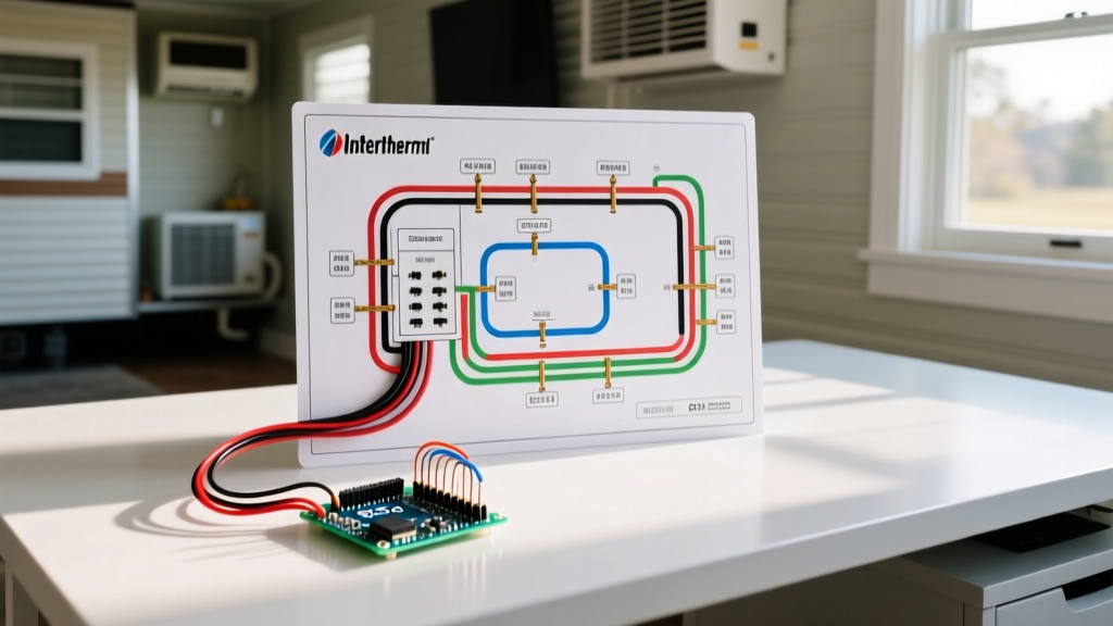
Decoding the Mobile Home Intertherm Electric Furnace Wiring Diagram
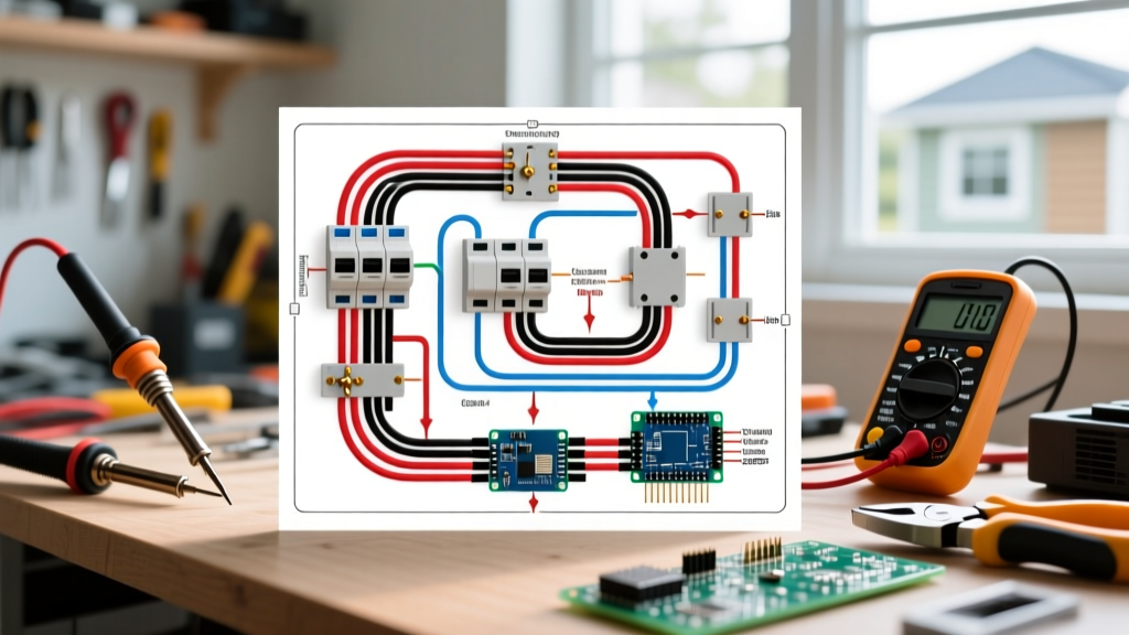
The Intertherm wiring schematic is divided into two distinct circuits: the 240V high-voltage power supply and the 24V low-voltage thermostat control circuit. Understanding how the sequencers bridge these two systems is the key to a successful installation.
High-Voltage Circuit Requirements (240V)
Power enters the furnace through a knock-out on the blower compartment and connects to the main terminal block or directly to the first sequencer. Intertherm units utilize time-delay sequencers (often manufactured by White-Rodgers or Johnson Controls) to stage the heating elements. This prevents a massive inrush current that would trip the main breaker if all nickel-chromium heating elements engaged simultaneously.
- Line 1 (L1) and Line 2 (L2): 240V enters the sequencer coils and the heating element contacts.
- Sequencer Staging: When 24V is applied to the first sequencer coil, its bimetallic strip heats up, closing the high-voltage contacts for Element 1 and the blower motor relay. Subsequent sequencers close at 15-second to 30-second intervals.
- Limit Switches: The wiring diagram will show auto-reset and manual-reset limit switches wired in series with the sequencer coils or the heating elements to prevent overheating in the event of blower failure.
Low-Voltage Thermostat Control Wiring
The control circuit steps down 240V to 24V using an internal transformer (typically 40VA). For standard heating-only or heat-pump configurations, you will route an 18/5 or 18/8 AWG thermostat cable from the wall thermostat to the furnace control board or terminal strip.
- R (Red): 24V Hot from the transformer.
- W (White): Heat call (energizes the sequencer coils).
- G (Green): Fan-only call (energizes the blower relay without the heat strips).
- C (Blue/Black): 24V Common (required for smart thermostats like Nest or Ecobee).
Wire Gauge and Breaker Sizing Matrix
Selecting the correct overcurrent protection and wire gauge is non-negotiable. The following matrix aligns with standard Intertherm specifications and NEC Article 310 ampacity tables for copper conductors with 75°C terminations.
| Furnace Model / kW | Max Ampacity | Required Breaker (Double-Pole) | Min. Copper Wire Gauge (THHN/UF-B) |
|---|---|---|---|
| E5EB-010 (10kW) | 41.6A | 50 Amp | 6 AWG |
| E3EB-012 (12kW) | 50.0A | 60 Amp | 6 AWG |
| E5EB-015 (15kW) | 62.5A | 70 Amp | 4 AWG |
| E5EB-020 (20kW) | 83.3A | 90 Amp or Dual 50A* | 3 AWG or Dual 6 AWG* |
*Note: Some 20kW Intertherm models are factory-configured with a split-circuit harness requiring two separate 50A breakers and two 6 AWG feeds. Always verify the specific unit's schematic.
Step-by-Step Installation Planning Workflow
To ensure a smooth installation day, follow this structured planning workflow. Budget approximately $150 to $350 for electrical materials (breakers, wire, conduit, disconnects) and 4 to 6 hours for labor.
- Disconnect Power: Shut off the main breaker and verify zero voltage at the panel using a CAT III or CAT IV multimeter.
- Install the Disconnect: Mount a 240V, 60A non-fused (or fused, per local code) AC disconnect box within sight of the furnace, typically on the exterior wall or an adjacent interior stud.
- Pull the Feeder Wire: Route the UF-B or THHN conductors from the main panel to the disconnect, and from the disconnect to the furnace junction box. Maintain a 1.25-inch clearance from gas lines or HVAC ducting.
- Terminate High Voltage: Torque the breaker and disconnect lugs to the manufacturer's specified inch-pound rating (usually 40-50 in-lbs for 6 AWG). Connect L1 and L2 to the furnace terminal block.
- Wire the Thermostat: Route the 18/5 control wire through the chassis grommet. Connect R, W, G, and C to the designated terminal strip.
- Configure Blower Speed Taps: Mobile home ductwork operates at higher static pressure. Adjust the blower motor speed tap (typically the Red or White wire for medium-low/low speed) to ensure adequate CFM without tripping the high-limit switch.
Common Wiring Failure Modes and Edge Cases
Even with a correct diagram, field conditions can introduce faults. Be aware of these specific Intertherm failure modes:
Sequencer Coil Burnout
If the 24V transformer is failing or the thermostat wire run exceeds 50 feet without a thicker gauge (e.g., 16 AWG), voltage drop can occur. A sequencer coil receiving only 18V to 20V may chatter, overheat, and eventually burn out. Solution: Verify 24V AC at the sequencer coil terminals while the thermostat is calling for heat.
Blower Motor Overheating on High Tap
Manufactured home trunk lines are often undersized compared to site-built homes. If the blower motor is left on the Black (High) speed tap, the motor will struggle against the high static pressure, draw excessive amperage, and trip its internal thermal overload. Solution: Always reference the Intertherm blower performance chart and default to the Medium-Low tap for heating operations.
Chassis Grounding Issues
The metal chassis of a mobile home must be properly bonded to the electrical system's grounding electrode. If the furnace chassis is not bonded to the panel's ground bus via the equipment grounding conductor (EGC), a short to the casing will not trip the breaker, creating a lethal shock hazard. Ensure the bare copper or green EGC is securely terminated to the furnace's designated green grounding screw.
Safety and Code Compliance
Compliance is not optional when dealing with high-amperage heating appliances in confined spaces. The National Fire Protection Association (NFPA 70 / NEC) dictates all wire sizing, overcurrent protection, and routing methods. Furthermore, the HUD Manufactured Housing Program enforces strict clearance and combustion/ventilation safety standards (24 CFR Part 3280) that dictate how HVAC equipment integrates with the home's structural chassis and vapor barriers. Finally, consult the U.S. Department of Energy's heating and cooling guidelines to ensure your electrical setup supports optimal system efficiency and smart thermostat integration.
By meticulously planning your wire routes, respecting the sequencer logic, and adhering to the specific ampacity requirements of your Intertherm model, you will achieve a safe, efficient, and code-compliant heating system capable of enduring the harshest winter conditions.