
Why Code Compliance Dictates Your 60 Amp Subpanel Wiring Diagram
Installing a 60-amp subpanel is one of the most common electrical upgrades for modern properties, whether you are powering a detached garage, a heavy-duty workshop, or preparing for a Level 2 EV charger. However, executing a safe and functional wiring diagram for 60 amp subpanel configurations requires strict adherence to the National Electrical Code (NEC). A flawed installation doesn't just risk tripping breakers; it introduces severe shock hazards, fire risks, and guaranteed inspection failures.
From a safety and code compliance perspective, the transition from the main service panel to a remote subpanel hinges on three critical NEC mandates: proper feeder sizing, the strict separation of neutral and ground buses, and the correct implementation of a Grounding Electrode System (GES) for detached structures. According to the NFPA NEC Guidelines, electrical fires and failures are overwhelmingly linked to improper terminations and grounding faults. This guide breaks down the exact specifications, material requirements, and execution steps to ensure your 60A subpanel is safe, legal, and inspection-ready in 2026.
Essential Materials & 2026 Sizing Specifications
Before pulling any wire, you must procure materials that meet current UL listings and NEC ampacity tables. Undersizing your feeder or using the wrong conduit type are immediate red flags for electrical inspectors.
| Component | Specification / Model Example | NEC Reference | Est. 2026 Cost |
|---|---|---|---|
| Main Breaker | 60A Double-Pole (e.g., Square D HOM260) | Article 240 | $12 - $18 |
| Feeder Wire (Copper) | 6 AWG THHN/THWN-2 (4 strands: 2 Black, 1 White, 1 Green) | Table 310.16 | $1.80 / ft |
| Feeder Wire (Aluminum) | 4 AWG SER Cable (4-wire) | Table 310.16 | $1.40 / ft |
| Conduit (Outdoor/Underground) | 1-inch PVC Schedule 80 | Article 352 | $4.50 / ft |
| Subpanel Enclosure | 100A Main Lugs, 12-24 Spaces (e.g., Siemens P212100) | Article 408 | $65 - $85 |
| Grounding Electrodes | Two 5/8" x 8' Copper-Clad Steel Rods | 250.53(A)(2) | $35 (pair) |
Step-by-Step Wiring Diagram Execution
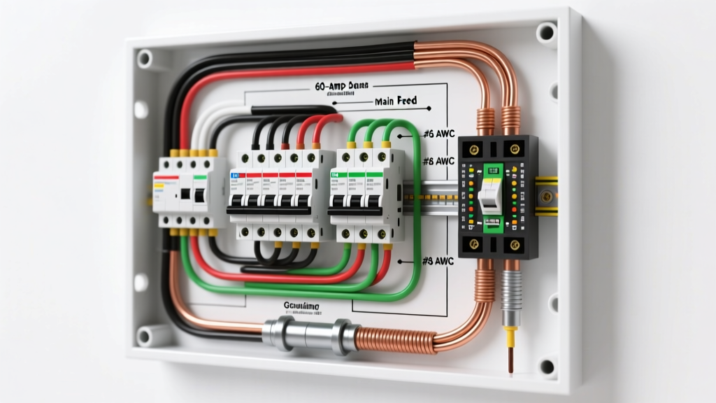
The physical wiring diagram for a 60 amp subpanel involves three distinct zones: the origin (main panel), the run (feeder conduit), and the destination (subpanel). Here is how to execute each phase safely.
1. Main Panel Feed & Disconnect
At the main service panel, your 60A subpanel feed originates at a dedicated 2-pole, 60-amp breaker.
- Termination Torque: NEC 110.14(D) mandates that all terminations be torqued to the manufacturer's specifications. For a Square D HOM260 breaker accepting 6 AWG copper, the required torque is typically 35 in-lbs. Use a calibrated torque screwdriver (like the Klein Tools 69060) to prevent loose connections that cause arcing and thermal failure.
- Neutral & Ground Origin: In the main panel, the neutral and ground buses are bonded. Your white neutral wire lands on the neutral bar, and your green/bare ground wire lands on the ground bar or the panel's grounding lug.
2. Feeder Routing & Conduit Fill
If you are running THHN/THWN-2 wires through PVC conduit to a detached structure, you must adhere to NEC Chapter 9, Table 1 for conduit fill. A 1-inch Schedule 80 PVC conduit easily accommodates four 6 AWG wires while maintaining the required 40% fill capacity limit.
Safety Warning: Never pull wires through conduit with sharp bends without using wire pulling lubricant (e.g., Polywater). Dry pulling can strip the THHN insulation, creating a hidden ground-fault hazard that will only reveal itself when moisture enters the conduit underground.For direct burial without conduit, you must use UF-B cable, but for a 60A circuit, 4 AWG UF-B is required and must be buried at a depth of 24 inches per NEC Table 300.5. Using THHN in 1-inch PVC buried at 18 inches is generally the more cost-effective and inspection-friendly route.
3. Subpanel Termination & The Neutral/Ground Split
This is the most critical safety juncture in your wiring diagram. In a subpanel, the neutral and ground must NEVER be bonded.
- Isolate the Neutral: Remove the green bonding screw or bonding strap from the subpanel's neutral bus bar. The white neutral feeder wire must land on this isolated neutral bar.
- Ground the Enclosure: The green equipment grounding conductor (EGC) lands on a separate, dedicated ground bus bar that is physically bolted to the metal subpanel enclosure.
- Why this matters: If you bond neutral and ground in a subpanel, normal neutral return current will travel back to the main panel via both the neutral wire AND the ground wire. This energizes the grounding system, meaning any appliance chassis or metal conduit connected to the ground could carry lethal current.
Critical NEC Code Violations to Avoid
Electrical inspectors and safety auditors, guided by standards from organizations like OSHA's Electrical Safety protocols, look for specific failure modes during subpanel inspections. Avoid these common violations:
- Missing Disconnecting Means (Detached Structures): Per NEC 220.33 and 250.32, a detached garage or shed fed by a subpanel requires a local disconnecting means. If your subpanel has a main breaker (e.g., a 60A main breaker panel instead of main lugs), this satisfies the requirement. If using main lugs, you must install a separate 60A disconnect switch outside the structure.
- Undersized Grounding Electrode Conductor (GEC): For a 60A subpanel at a detached building, the GEC connecting the subpanel's ground bar to the exterior ground rods must be sized per NEC Table 250.66. For 6 AWG copper feeder wire, an 8 AWG bare copper GEC is the minimum requirement. Do not use 10 AWG or 12 AWG for this connection.
- Improper Ground Rod Spacing: If the first ground rod yields a resistance-to-ground of more than 25 ohms (which is true for most dry or rocky soils), NEC 250.53(A)(2) requires a second rod. The second rod must be driven at least 6 feet away from the first to ensure they do not share the same sphere of influence in the soil.
Voltage Drop Calculations for Long Runs
While the NEC does not strictly enforce voltage drop for branch circuits in all scenarios, NEC 310.15(B) recommends keeping voltage drop under 3% for feeders and 5% overall. For a 60-amp subpanel, a 3% drop at 240V equals a maximum loss of 7.2 volts.
The 100-Foot Rule: If your subpanel is located less than 100 feet from the main panel, 6 AWG copper is perfectly adequate. However, if your run extends to 150 feet, 6 AWG copper will experience a voltage drop of roughly 4.1% at full 60A load. In this scenario, you must upsized your feeder to 4 AWG copper or 2 AWG aluminum to maintain code-recommended efficiency and prevent motor-starting failures in the workshop.
Final Inspection Prep & Safety Gear
Before energizing the panel, perform a continuity test with a multimeter to ensure there is zero continuity between the isolated neutral bus and the ground bus in the subpanel. Furthermore, ensure all unused knockouts in the subpanel enclosure are sealed with metal knockout seals to prevent rodent intrusion and maintain the panel's UL enclosure rating.
Always wear Category 2 Arc Flash PPE (including an 8 cal/cm² face shield and voltage-rated gloves) when terminating live feeder wires at the main panel. For comprehensive field-reference guides and code updates, industry professionals frequently consult Mike Holt Enterprises, a premier authority on NEC interpretation and electrical safety training. By respecting the physics of the circuit and the letter of the NEC, your 60-amp subpanel will provide decades of safe, reliable power.