
Integrating Stepper Motors into DIY Smart Appliances
When designing motorized smart appliances—such as automated HVAC zone dampers, precision liquid dosing valves for smart coffee machines, or motorized pet feeders—DC motors often lack the positional accuracy required. This is where the Arduino stepper motor wiring diagram becomes essential. By pairing a high-torque NEMA 17 stepper motor with an A4988 microstepping driver and an Arduino microcontroller, you can achieve sub-degree rotational accuracy without the need for complex optical encoders.
In this comprehensive appliance wiring tutorial, we will break down the exact schematic, component selection, current calibration, and failure-mode troubleshooting required to build a reliable, production-grade stepper motor circuit for your home automation or DIY appliance projects in 2026.
Bill of Materials (BOM) and 2026 Component Pricing
Before cutting wires, ensure you have the correct components. Using undersized power supplies is the number one cause of stepper motor failure in DIY appliances.
- NEMA 17 Stepper Motor (e.g., StepperOnline 17HS4401S): Rated at 1.5A to 1.7A per phase. Provides ~40 N·cm holding torque. ($12 - $16)
- A4988 Stepper Motor Driver Carrier: Handles up to 2A per coil with adequate cooling. ($3 - $5)
- Arduino Nano (ATmega328P): Compact footprint for appliance integration. As of 2026, genuine boards retail around $22, while high-quality CH340-chip clones are $7. ($7 - $22)
- 12V 2A DC Power Supply (24W minimum): Steppers draw peak current during direction changes; a 2A headroom prevents voltage sag. ($10 - $14)
- 100µF 25V Electrolytic Capacitor: Mandatory for inductive spike suppression. ($0.50)
- JST-XH 2.54mm Connectors & 20AWG Silicone Wire: For vibration-resistant appliance wiring. ($8 for a kit)
Identifying NEMA 17 Stepper Motor Coils with a Multimeter
A standard bipolar NEMA 17 stepper motor has four wires representing two distinct electromagnetic coils (Coil A and Coil B). Wiring these to the incorrect A4988 output pins will result in erratic jittering or a locked rotor.
The Continuity Test Method
- Set your digital multimeter to resistance (Ohms) or continuity mode.
- Test the wires in pairs. When you find a pair that shows a resistance reading (typically between 1.5Ω and 2.5Ω for a NEMA 17), you have identified one complete coil.
- Label these two wires as Coil 1 (e.g., 1A and 1B).
- The remaining two wires will also show continuity with each other but infinite resistance (OL) when tested against Coil 1. Label these as Coil 2 (2A and 2B).
Expert Tip: Bipolar stepper motors do not have a 'positive' or 'negative' coil wire. Swapping 1A and 1B will simply reverse the logical direction of the motor, which can be corrected in your Arduino code or by swapping the wires at the driver.
The Core Arduino Stepper Motor Wiring Diagram
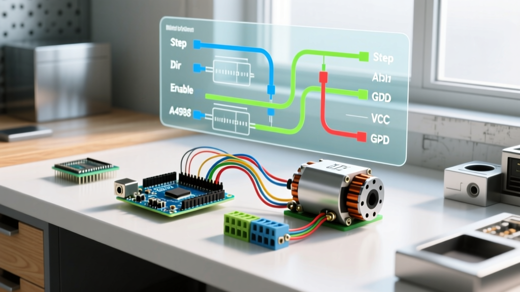
The A4988 driver isolates the high-current motor power from the sensitive logic circuits of the Arduino. Below is the definitive pinout mapping for your appliance build.
1. Power and Protection Circuit (VMOT & GND)
Connect your 12V DC power supply's positive terminal to the VMOT pin on the A4988, and the negative terminal to the GND pin. Crucial Step: Solder the 100µF electrolytic capacitor directly across the VMOT and GND pins on the driver board, observing the correct polarity (stripe on the capacitor goes to GND). According to the Pololu A4988 Stepper Motor Driver Carrier documentation, omitting this decoupling capacitor allows inductive voltage spikes from the motor coils to destroy the driver chip instantly upon connection.
2. Logic Power (VDD & GND)
Connect the Arduino's 5V output to the A4988 VDD pin, and a shared ground to the logic GND pin. The logic and motor grounds must be tied together for the control signals to register correctly.
3. Control Signal Pins
- STEP Pin: Connect to Arduino Digital Pin 3. Each HIGH pulse moves the motor one microstep.
- DIR Pin: Connect to Arduino Digital Pin 4. HIGH for clockwise, LOW for counter-clockwise.
- ENABLE Pin: Connect to Arduino Digital Pin 5 (or tie directly to GND to keep the driver perpetually enabled).
- SLEEP & RESET Pins: Jumper these two pins together with a short wire. If left floating, the driver will remain in sleep mode.
4. Motor Coil Outputs
Connect Coil 1 to 1A and 1B. Connect Coil 2 to 2A and 2B.
Critical Calibration: Setting the A4988 VREF
Out of the box, the A4988 current limit potentiometer is set to a random value. If set too high, the driver will overheat and trigger thermal shutdown, causing your appliance to stall mid-cycle. If set too low, the motor will lack the torque to move the mechanical load.
You must calibrate the VREF (Reference Voltage) using a multimeter and a ceramic flathead screwdriver (to prevent shorting the metal shaft to live components).
The VREF Calculation Formula
The formula for the A4988 is: VREF = (Max Current Limit) × 8 × Rsense
Most standard A4988 boards use a 0.05Ω Rsense resistor. If your NEMA 17 motor is rated for 1.5A per phase, but you are running it without active fan cooling, you should limit the current to 1.2A to prevent thermal throttling.
- Target Current: 1.2A
- Math: 1.2 × 8 × 0.05 = 0.48V
Power the A4988 logic side (VDD) with 5V from the Arduino, but leave VMOT disconnected for safety. Place your multimeter's black probe on the logic GND and the red probe on the metal body of the tiny potentiometer. Gently turn the screw until the multimeter reads exactly 0.48V.
Microstepping Configuration Matrix
For smooth appliance operation—such as quietly opening an HVAC damper without vibrating the ductwork—full-step mode is too aggressive. You must configure the MS1, MS2, and MS3 pins to enable microstepping. Note that MS3 requires a specific board trace to be cut or a specialized carrier board; standard breakout boards often only support up to 1/8th stepping without modification. Always verify against the Texas Instruments DRV8825 Datasheet if you upgrade to the higher-current DRV8825 alternative for heavier appliance loads.
| MS1 | MS2 | MS3 | Microstep Resolution | Best Appliance Use Case |
|---|---|---|---|---|
| LOW | LOW | LOW | Full Step | High-torque locking valves |
| HIGH | LOW | LOW | Half Step | Basic conveyor belts |
| HIGH | HIGH | LOW | Quarter Step | Standard motorized blinds |
| HIGH | HIGH | HIGH | Sixteenth Step | Precision liquid dosing pumps |
Appliance Code Integration: Why the Default Stepper Library Fails
When programming the Arduino for appliance control, many beginners rely on the default Arduino Stepper Library Documentation. While functional for basic testing, the default library uses a blocking, constant-velocity stepping method.
If you command a NEMA 17 motor to instantly jump from 0 to 1000 RPM to close a heavy smart-vent flap, the rotor will physically stall due to inertia. The motor will buzz loudly, draw maximum current, and fail to move. This is known as 'missed stepping'.
The AccelStepper Solution
For any real-world appliance, you must use the AccelStepper library. It implements trapezoidal acceleration and deceleration profiles. By defining a maximum speed and an acceleration rate (e.g., stepper.setMaxSpeed(800); stepper.setAcceleration(400);), the motor smoothly ramps up to speed, preserving torque and eliminating the jarring mechanical shock that destroys 3D-printed appliance gears.
Troubleshooting Common Failure Modes
Even with a perfect Arduino stepper motor wiring diagram, environmental factors in appliances (heat, vibration, EMI) can cause issues. Here is how to diagnose them:
- Motor Vibrates but Does Not Turn: The STEP pulse frequency in your code is too high for the current limit, or the acceleration is too steep. Lower the max speed in AccelStepper and verify your VREF calibration.
- A4988 Driver is Too Hot to Touch: The chip will throttle at ~165°C. If you are drawing more than 1A continuously, the A4988 requires an active cooling fan. For sealed appliance enclosures where fans aren't viable, upgrade to a TMC2209 silent driver, which runs significantly cooler and eliminates audible coil whine.
- Erratic Jittering or Random Steps: The STEP and DIR wires are acting as antennas, picking up electromagnetic interference (EMI) from nearby appliance compressors or AC lines. Use twisted-pair wiring for the STEP/DIR logic lines, and ensure they are routed at least 2 inches away from the 12V motor power cables.
- Motor Loses Position Over Time: Stepper motors are open-loop. If the mechanical load exceeds the holding torque (e.g., a jammed pet feeder kibble chute), the motor will skip steps, and the Arduino will have no way of knowing. Implement a simple microswitch limit sensor at the 'home' position to recalibrate the zero-point upon appliance startup.