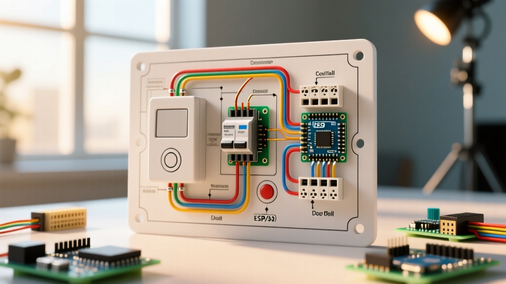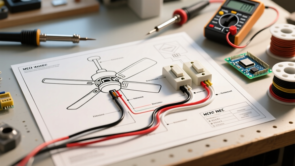

Pre-Installation Planning & 2026 NEC Code Requirements
When planning an independent fan and light control setup, understanding the exact wiring diagram for ceiling fan with 2 switches is only half the battle. The physical infrastructure—box volume, weight ratings, and cable routing—dictates the safety and longevity of the installation. Under the 2026 National Electrical Code (NEC), standard outlet boxes are strictly prohibited from supporting ceiling fans due to dynamic vibration loads.
NEC Article 422.18 mandates that ceiling fans must be supported by an outlet box specifically listed and marked for fan support. Furthermore, Article 314.16 dictates strict box fill calculations. A dual-switch setup requires a 3-wire cable (plus ground) running from the switch box to the ceiling box, significantly increasing the cubic inch volume required in both locations.
Ceiling Box Selection & Volume Matrix
Selecting the correct ceiling box prevents catastrophic failure. Below is a comparison of standard fan-rated boxes available in 2026, factoring in volume for 14/3 NM-B cable fills.
| Box Model | Type | Volume (cu in) | Max Weight Rating | Est. 2026 Cost |
|---|---|---|---|---|
| Raco 2800 | 4" Octagonal, Fan-Rated | 21.5 | 70 lbs | $12.50 |
| Carlon B618R | Round, Old-Work Fan Rated | 18.0 | 70 lbs | $14.25 |
| Hubbell HBL4100 | Heavy Duty Cast Iron | 24.0 | 150 lbs | $38.00 |
Expert Note: Always calculate box fill before drywall closure. For a 14/3 NM-B cable entering the ceiling box, you must account for 4 current-carrying conductors (if counting the neutral), the equipment grounding conductor (1), and the internal clamps (1). This equates to roughly 12 cubic inches of fill just for the cable entry, leaving minimal room for wire nuts in an 18 cu in box. Opt for the 21.5 cu in Raco 2800 to ensure adequate working space.
Understanding the Wiring Diagram for Ceiling Fan With 2 Switches
The core of this configuration relies on running a continuous 14/3 or 12/3 NM-B (Romex) cable from a double-gang switch box to the ceiling box. This allows the single hot feed to be split into two independently switched legs at the wall, while sharing a single neutral return path.
Wire Color Assignment & Routing Strategy
- Black Wire (14/3): Switched hot for the ceiling fan motor. Connects to the top switch load terminal and the fan's black (or blue) motor wire.
- Red Wire (14/3): Switched hot for the light kit. Connects to the bottom switch load terminal and the fan's blue (or white) light kit wire.
- White Wire (14/3): Shared neutral. Bypasses the switches entirely, wire-nutted in the switch box, and connects to the white neutral wires at the ceiling canopy.
- Bare Copper (14/3): Equipment grounding conductor. Must be bonded to the metal switch box, both switch yokes, the ceiling box, and the fan mounting bracket.
Component Selection: Switches, Wire Gauge, and Connectors
A common failure mode in dual-switch ceiling fan installations is the improper use of dimmers on fan motors. Standard TRIAC-based dimmers will cause AC induction motors to hum violently, overheat, and eventually fail, posing a severe fire risk.
Switch Configuration Matrix
| Component | Recommended 2026 Model | Application | Price Range |
|---|---|---|---|
| Fan Switch | Leviton Decora 15A (5601-2W) | Standard On/Off for Motor | $4.75 |
| Fan Speed Control | Lutron Diva Fan Speed (DVFSQ-LF) | Variable Motor Speed (Quiet) | $34.50 |
| Light Dimmer | Lutron Diva LED+ (DVCL-153P) | Dimming LED Light Kits | $28.50 |
| Wire Connectors | WAGO 221-413 Lever-Nuts | 3-Port Splicing (12-24 AWG) | $0.48 / ea |
Cable Selection: For a 15-amp breaker circuit, Southwire 14/3 NM-B (approx. $0.68/ft) is standard. If the circuit is rated for 20 amps, you must upgrade to 12/3 NM-B (approx. $0.89/ft) to comply with NEC Article 240.4(D).
Step-by-Step Termination Strategy
Proper termination ensures low-resistance connections and prevents thermal expansion from loosening screws over years of vibration.
- Rough-In the Cable: Pull the 14/3 NM-B through the framing. Leave at least 8 inches of slack extending past the face of the drywall at both the switch and ceiling boxes.
- Strip the Jacket: Remove exactly 10 inches of the outer PVC jacket. Do not nick the inner THHN insulation.
- Prepare the Conductors: If using WAGO 221 Lever-Nuts, strip the individual wires to exactly 11mm (7/16 inch). If using Ideal INDUSTRIES In-Sure push-in connectors, strip to 1/2 inch.
- Switch Box Pigtailing: The incoming hot (Line) must be pigtailed to feed both switches. Use a 6-inch piece of 14 AWG black THHN wire and a WAGO 221-413 to splice the Line, Pigtail 1 (Fan Switch), and Pigtail 2 (Light Switch).
- Terminate the Switches: Loop the stripped wire clockwise around the brass terminal screws. Tighten to 14 in-lbs of torque. Do not use the back-stab push-in holes on standard switches; they are prone to arcing under motor startup loads.
- Canopy Connections: At the ceiling, connect the 14/3 Black to the Fan Black, 14/3 Red to the Fan Blue (Light), and bundle all Whites together. Bond all bare grounds to the green grounding screw on the fan mounting bracket.
Common Failure Modes & Troubleshooting Edge Cases
Even with a perfect wiring diagram for ceiling fan with 2 switches, modern electrical environments introduce unique edge cases that require proactive planning.
1. LED Ghosting and Phantom Voltage
If your light kit uses low-wattage LED bulbs, you may notice them glowing faintly when the switch is off. This is caused by induced voltage on the red wire running parallel to the live black wire in the 14/3 cable over long distances (typically over 40 feet). Solution: Install a Lutron LUT-MLC (Capacitive Load Resistor) across the hot and neutral at the light fixture, or ensure you are using advanced digital dimmers like the Lutron DVCL-153P which manage leakage current internally.
2. Multi-Wire Branch Circuit (MWBC) Hazards
If your switch box is fed by a 12/3 or 14/3 cable from the panel acting as an MWBC (sharing a neutral between two 120V legs on a 240V split-phase system), NEC Article 210.4(B) requires a simultaneous disconnect mechanism. You must install a 2-pole breaker or a handle-tie on two adjacent single-pole breakers. Failing to do this means the shared neutral at the ceiling box could carry the sum of both currents if one breaker is turned off, leading to a melted neutral and potential fire.
3. Motor Humming on Dimmers
If a homeowner mistakenly wires the fan motor to the Lutron DVCL-153P light dimmer, the motor will emit a loud 60Hz hum. This occurs because the dimmer chops the AC sine wave, which the induction motor cannot process. Always verify the load type before terminating the switches. If variable fan speed is desired, you must swap the standard toggle for a dedicated fan speed control module (e.g., Lutron DVFSQ-LF) which utilizes stepped voltage tapping rather than phase-cutting.
Final Inspection Checklist
Before energizing the circuit and installing the decorative canopy cover, verify the following:
- All equipment grounding conductors are bonded to metal boxes and the fan bracket.
- No bare copper is exposed outside of wire connectors or terminal screws.
- The ceiling box is securely fastened to the structural framing (joist or blocking), not just the drywall.
- The total weight of the fan assembly does not exceed the rated capacity of the outlet box.
For further reading on energy-efficient fan motor specifications and aerodynamic testing standards, refer to the ENERGY STAR Ceiling Fan Specifications. Proper planning using this guide ensures your dual-switch installation is not only functional but fully compliant with modern safety standards. For deeper dives into NEC box fill math and advanced residential wiring, Mike Holt Enterprises remains the premier educational resource for electrical professionals.