
Planning Your GE Electric Dryer Installation: Beyond the Basics
Installing a new GE electric dryer—whether it is a high-capacity 7.2 cu. ft. model like the GTD72EBSNWS or a compact unitized spacemaker like the GUD24ESSMWW—requires more than just plugging in a cord. As of 2026, local building inspectors strictly enforce the National Electrical Code (NEC) mandates for dedicated 240-volt circuits, proper grounding, and specific wire gauges. Relying on a generic wiring diagram for GE electric dryer setups without understanding the underlying electrical architecture can lead to tripped breakers, damaged heating elements, or severe fire hazards.
This installation planning guide breaks down the exact wiring schematics, terminal block configurations, and material requirements you need before pulling a single wire.
Anatomy of the GE Dryer Terminal Block
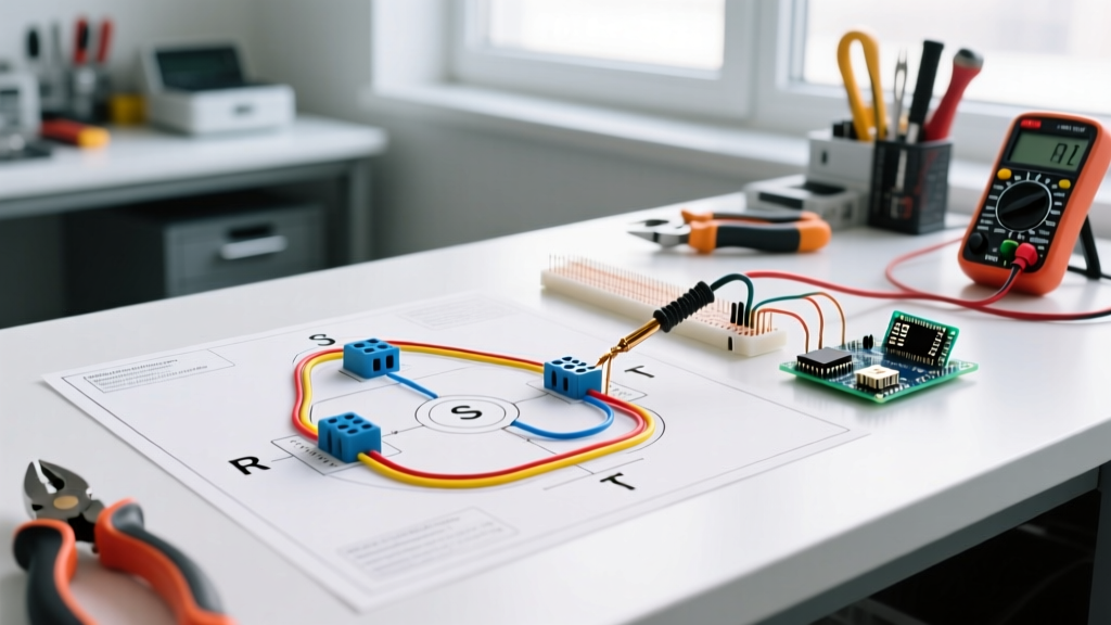
The heart of your dryer's electrical connection is the terminal block, located at the rear of the unit behind a metal access panel. Understanding how to read the wiring diagram for your specific GE model is critical. Modern GE electric dryers utilize a dual-voltage system:
- 240V Circuit (L1 to L2): Powers the high-wattage heating element (typically 4,500W to 5,500W).
- 120V Circuit (L1 to Neutral & L2 to Neutral): Powers the drum motor, control board, LED display, and interior lighting.
When you consult the GE Appliances official support documentation, you will notice the terminal block features three or four primary screw terminals. For a standard 4-wire installation, the left terminal is L1 (Black/Hot), the center terminal is Neutral (White), and the right terminal is L2 (Red/Hot). The ground wire (Green/Bare) bypasses the terminal block entirely and connects directly to the dryer's metal chassis via a dedicated green grounding screw.
The 3-Prong vs. 4-Prong Configuration Debate
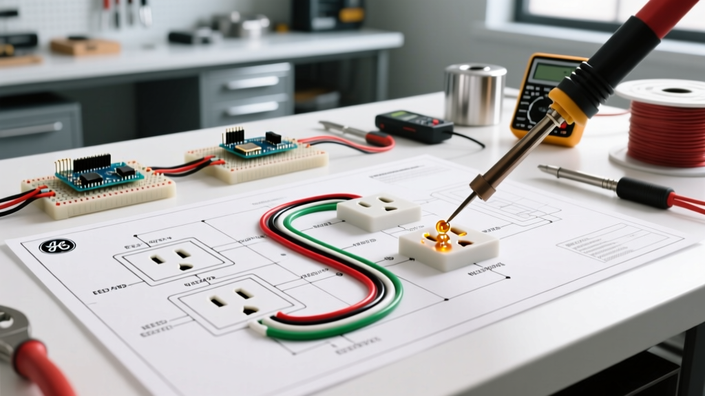
One of the most common points of confusion during installation planning is choosing between a 3-prong and 4-prong power cord. The NEC (specifically Article 250.140) strictly requires 4-prong receptacles and cords for all new residential construction and new dryer installations as of the 2023 and 2026 code cycles.
| Feature | 3-Prong Setup (Legacy) | 4-Prong Setup (Current NEC Standard) |
|---|---|---|
| Cord Type | NEMA 10-30 (10 AWG, 3-wire) | NEMA 14-30 (10 AWG, 4-wire) |
| Receptacle | NEMA 10-30R | NEMA 14-30R |
| Grounding Method | Neutral bonded to chassis via ground strap | Separate dedicated equipment grounding conductor |
| NEC Compliance (2026) | Only permitted in existing, unmodified older homes | Mandatory for all new installations and renovations |
Critical Warning: The Ground Strap
Installation Alert: If you are converting a GE dryer from a 3-prong to a 4-prong cord, you must remove or isolate the metal ground strap that connects the center neutral terminal to the dryer chassis. Leaving this strap in place on a 4-wire system creates a parallel neutral path, which can energize the dryer's metal exterior and result in a lethal shock hazard.
Pre-Installation Electrical Requirements & Wire Sizing
Before purchasing materials, verify your electrical panel's capacity and the physical distance to the laundry room. According to the National Fire Protection Association (NFPA), a standard electric dryer requires a dedicated 30-amp, 240-volt circuit.
Wire Gauge and Voltage Drop Calculations
For a standard 30-amp circuit, the minimum allowable wire size is 10 AWG copper (or 8 AWG aluminum). However, wire length dictates voltage drop. The U.S. Department of Energy notes that modern dryers with advanced moisture sensors and smart boards are highly sensitive to voltage fluctuations. If your cable run from the main panel to the receptacle exceeds 75 feet, you must upgrade to 8 AWG copper wire to maintain a voltage drop below the recommended 3% threshold. Using 10 AWG on a 100-foot run will result in roughly a 5% voltage drop, causing the heating element to underperform and extending dry times.
Breaker Selection
Always use a 2-pole, 30-amp circuit breaker with an internal common trip mechanism (e.g., Square D QO230 or Eaton BR230). Do not use two single-pole 30A breakers with a handle tie; while occasionally seen in older panels, modern 2026 electrical inspections frequently flag this as a violation due to the lack of simultaneous internal tripping during a fault.
Step-by-Step Terminal Block Wiring Guide
Follow this precise sequence when terminating the wires on your GE dryer. Always ensure the main breaker is locked out and tagged out (LOTO) before beginning.
- Install the Strain Relief: GE requires a specific strain relief clamp to prevent the cord from pulling out of the terminal block. For a 4-prong cord, use the GE part number WX081004. Insert it into the 1.5-inch knockout hole at the bottom rear of the dryer and tighten the locknut.
- Thread the Cord: Pass the 4-wire cord through the strain relief. Ensure the cord jacket extends at least 1 inch inside the cabinet to prevent the individual wires from bearing the mechanical stress.
- Strip the Wires: Strip exactly 3/4 inch of insulation from the Black, White, Red, and Green wires. Do not nick the copper strands, as this creates a localized hot spot that can melt the terminal block over time.
- Connect the Ground: Route the Green wire to the external chassis ground screw (usually painted green or marked with a ground symbol on the lower back panel). Tighten securely.
- Terminate the Neutral: Connect the White wire to the center terminal block screw. This is the most critical connection; a loose neutral will cause 120V components to experience severe voltage fluctuations.
- Terminate the Hots: Connect the Black wire to the left terminal (L1) and the Red wire to the right terminal (L2). Polarity between L1 and L2 does not matter for AC heating elements, but maintaining standard color coding is best practice for future troubleshooting.
- Torque and Verify: Tighten all terminal screws firmly. Tug gently on each wire to ensure it is seated. Replace the metal access cover.
Common Wiring Failure Modes & Troubleshooting
Even with a perfect wiring diagram for your GE electric dryer, installation errors can manifest in specific ways. Here is how to diagnose them using a multimeter:
- Dryer Tumbles but Produces No Heat: This indicates a loss of 240V. The motor runs on 120V (L1 to Neutral), but the heater needs L1 to L2. Check the breaker panel for a tripped half of the double-pole breaker, or test the receptacle. You should read 240V across the two angled hot slots.
- Control Board is Dead, No Lights: This usually points to an open Neutral. If the White wire is loose on the center terminal, the 120V control circuit cannot complete its path.
- GFCI/AFCI Breaker Nuisance Tripping: If your laundry room is on an AFCI/GFCI breaker (increasingly common in 2026 code updates), ensure the neutral and ground are completely separated at the dryer. A lingering ground strap will cause the GFCI to detect a ground fault and trip immediately upon starting the motor.
2026 Material Cost & Planning Breakdown
Budgeting for a new dryer circuit installation requires accounting for current copper prices and smart-panel components. Below is a realistic cost estimate for a standard 40-foot run using 10/3 NM-B (Romex) cable.
| Material / Component | Specification | Estimated Cost (2026) |
|---|---|---|
| 10/3 NM-B Cable | 40 feet (includes ground) | $65.00 - $80.00 |
| 2-Pole 30A Breaker | Square D QO or Eaton BR | $18.00 - $25.00 |
| NEMA 14-30R Receptacle | Leviton or Hubbell heavy-duty | $15.00 - $22.00 |
| GE 4-Prong Power Cord | WX081004 (6 ft, 30A) | $25.00 - $35.00 |
| Miscellaneous | Cable staples, wall plate, wire nuts | $12.00 |
| Total Estimated Material Cost | $135.00 - $174.00 | |
By meticulously planning your installation and adhering strictly to the wiring diagram for your specific GE electric dryer model, you ensure optimal performance, compliance with the latest NEC standards, and long-term safety for your home's electrical infrastructure.