
Mastering the 24v Wiring Diagram for Trolling Motors
Wiring a 24-volt trolling motor requires more than just connecting batteries to a propeller. Modern brushless motors, such as the Garmin Force and Lowrance Ghost, draw immense transient current—often exceeding 60 amps under heavy load or in strong currents. If your 24v wiring diagram for trolling motors relies on undersized wire or incorrect overcurrent protection, you risk severe voltage drop, melted insulation, or catastrophic logic board failures.
This comprehensive guide breaks down the exact American Boat & Yacht Council (ABYC) E-11 standards for marine wire gauge selection, color-coding protocols, and breaker sizing. Whether you are rigging a new bass boat or upgrading an aluminum hull, these specifications ensure your 24V system delivers maximum thrust and longevity in 2026 and beyond.
The Anatomy of a 24V Series Circuit
A 24-volt trolling motor system utilizes two 12V deep-cycle marine batteries (typically Group 27 or Group 31) wired in series. Wiring in series doubles the voltage (12V + 12V = 24V) while maintaining the same amp-hour (Ah) capacity as a single battery.
Expert Note: Never wire your two 12V batteries in parallel for a 24V motor. Parallel wiring keeps the voltage at 12V while doubling the Ah capacity, which will instantly destroy a 24V trolling motor's control board and void your warranty.
The Core Connection Path
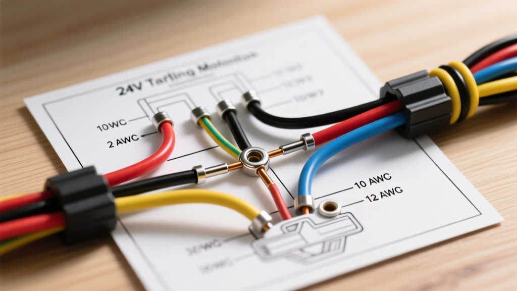
- Motor Positive (+): Connects to the Positive (+) terminal of Battery 1.
- The Series Jumper: Connects the Negative (-) terminal of Battery 1 to the Positive (+) terminal of Battery 2.
- Motor Negative (-): Connects to the Negative (-) terminal of Battery 2.
ABYC-Compliant Wire Gauge Sizing Chart
The most common failure point in aftermarket trolling motor installations is the use of automotive-grade Copper Clad Aluminum (CCA) wire or undersized American Wire Gauge (AWG) ratings. According to ABYC Standards, marine environments demand UL 1426 listed, tinned copper wire to resist galvanic corrosion and vibration fatigue.
As of 2026, premium marine-grade tinned copper wire costs between $1.80 and $3.50 per foot depending on the gauge. Do not compromise on this material.
| AWG Size | Max Continuous Amps | Max Run Length (One-Way) | Ideal Motor Application |
|---|---|---|---|
| 6 AWG | 60A | Up to 15 feet | 55 lb - 70 lb thrust (e.g., Minn Kota PowerDrive) |
| 4 AWG | 80A | Up to 20 feet | 80 lb thrust (e.g., Garmin Force, Minn Kota Terrova) |
| 2 AWG | 105A | Up to 25 feet | 90 lb - 112 lb thrust (e.g., Lowrance Ghost, Ultrex 112) |
| 1/0 AWG | 150A | Up to 30+ feet | Custom multi-motor setups or extreme cable runs |
Note: "Max Run Length" refers to the distance from the battery bank to the motor plug. If your run exceeds the listed distance, you must step up to the next thickest wire gauge to maintain a voltage drop below 3%.
Marine Color Code Standards for 24V Systems
Adhering to standard marine color codes is critical for troubleshooting and safety. When a marine electrician or a fellow angler opens your battery compartment, the wire colors should instantly communicate the circuit's function. The BoatUS wiring guidelines heavily emphasize these ABYC color standards to prevent accidental short circuits.
| Wire Color | ABYC Designation | 24V Trolling Motor Application |
|---|---|---|
| Red | Positive Primary | Main positive feed from Battery 1 to the trolling motor plug. |
| Black | Negative Primary | Main negative feed from Battery 2 to the trolling motor plug. |
| Yellow | Series Jumper / 24V Tap | The critical jumper connecting Battery 1 (-) to Battery 2 (+). |
| Orange | 12V Accessory Tap | Used if a 12V/24V selector switch or DC-DC charger is installed. |
Overcurrent Protection: Breakers and Fuses
Every ungrounded (positive) conductor must be protected by an overcurrent device. For 24V trolling motors, ABYC mandates that the circuit breaker or fuse be installed within 7 inches of the battery positive terminal. If the physical layout makes this impossible, the absolute maximum distance is 72 inches, provided the wire is enclosed in a continuous protective sheath.
Thermal Magnetic Breakers vs. ANL Fuses
- Thermal Reset Breakers (e.g., Blue Sea Systems 4808 60A or 4810 80A): These are the industry standard for trolling motors. They feature a manual reset lever and are designed to trip during sustained overloads or short circuits. Cost: ~$45 to $65.
- ANL Fuses (e.g., Blue Sea 80A ANL): Preferred for high-draw brushless motors (like the 112 lb thrust models) where transient startup spikes might nuisance-trip a thermal breaker. Requires a separate fuse block. Cost: ~$25 for the fuse and block.
Advanced Configurations: 12V/24V Selector Switches
A common dilemma in 24V systems is how to run 12V accessories (livewell pumps, graph power, LED deck lights) without draining just one of the 12V batteries, which leads to severe battery imbalance and premature death of the depleted battery.
To solve this, integrate a 12V/24V Battery Equalizer or DC-DC Charger (such as the Minn Kota MKR-20 or Pro Charging Systems 12V/24V selector).
Wiring the Equalizer:
- Connect the equalizer's 24V input across the main positive (Battery 1) and main negative (Battery 2).
- The equalizer steps the voltage down to 12V and draws power equally from both batteries.
- Route the 12V output (using Orange wire) to your boat's 12V accessory bus bar.
Step-by-Step Termination and Weatherproofing
The marine environment is hostile to electrical connections. Salt spray, freshwater humidity, and constant hull vibration will destroy poorly terminated wires. Follow this exact termination protocol:
- Strip and Clean: Strip the wire using a precision gauge stripper. Do not nick the copper strands.
- Crimp, Never Solder: Use marine-grade, adhesive-lined heat shrink terminals (e.g., Ancor or 3M). Solder wicks into wire strands under vibration, creating a brittle point that will eventually snap. A proper ratchet crimp is mechanically superior on a boat.
- Seal with Heat: Apply heat to the adhesive-lined heat shrink until the inner sealant melts and oozes slightly from the edges. This creates a 100% waterproof barrier against capillary corrosion.
- Quick Disconnects: At the deck plug, use heavy-duty Anderson Powerpole SB50 or marine-specific twist-lock trolling motor plugs rated for at least 60A continuous.
Troubleshooting Matrix: Common 24V Failures
When your motor fails to deploy or loses power mid-fight with a trophy fish, use this diagnostic matrix to identify the root cause based on your wiring configuration.
| Symptom | Root Cause | Technical Fix |
|---|---|---|
| Motor logic board resets at max speed | Voltage drop exceeding 10% due to undersized wire or corroded deck plug. | Upgrade to 2 AWG tinned copper; clean plug contacts with dielectric grease. |
| One battery dies much faster than the other | 12V accessories are wired directly to Battery 1 without an equalizer. | Install a 12V/24V DC-DC battery equalizer to balance the draw. |
| Breaker trips immediately upon engaging prop | Short circuit in the lower unit, or breaker amperage is rated too low for startup surge. | Test lower unit for shorts; upgrade to an ANL fuse setup for high transient tolerance. |
| Intermittent power loss in choppy water | Vibration-induced fracture in a soldered connection or loose battery wingnut. | Replace soldered joints with ratcheted adhesive heat-shrink crimps; use locking nylon nuts. |
Final Verification Steps
Before launching, use a digital multimeter to verify your deck receptacle. You should read exactly 24.0V to 25.6V (depending on the state of charge of your AGM or Lithium batteries) between the Red and Black pins. If you read 12V, your series jumper is disconnected or wired in parallel. If you read 0V, check your main thermal breaker. For comprehensive installation manuals specific to your motor model, always refer to the official Minn Kota support manuals or your respective manufacturer's documentation.