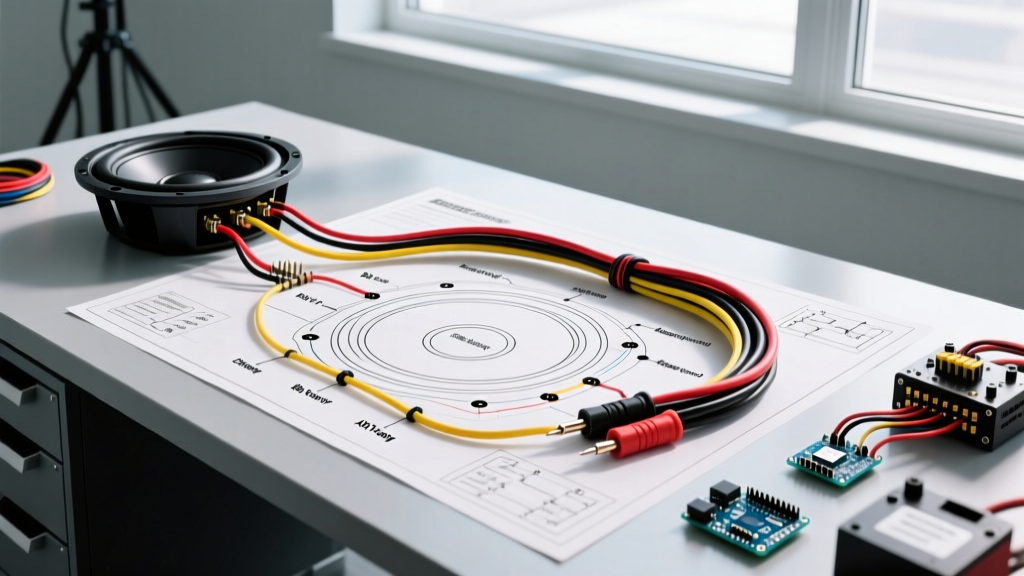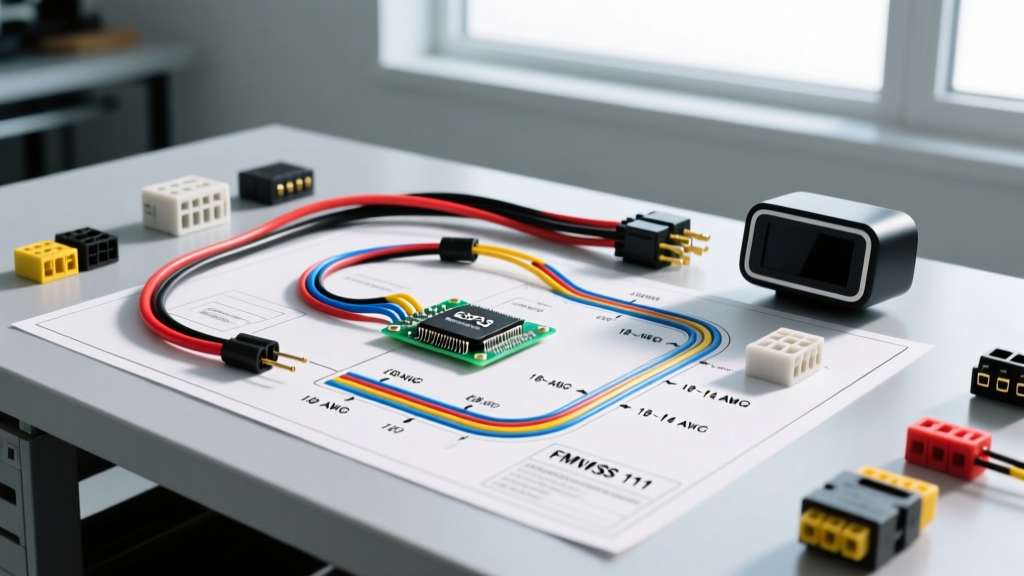

The Hidden Dangers of 'Quick-Tap' Camera Wiring
When installing an aftermarket backup camera, the most common advice found on forums is to 'simply tap into the reverse light wire.' While this works on vehicles manufactured before 2010, applying this outdated logic to modern vehicles is a fast track to electrical failure. Modern automotive electrical systems rely on Body Control Modules (BCMs) and Pulse Width Modulation (PWM) to monitor bulb health and manage power delivery. Tapping directly into a PWM-controlled reverse light circuit without isolation will result in severe camera flickering, CAN bus 'bulb out' errors, and in worst-case scenarios, a short circuit that can fry a $1,500 BCM.
Furthermore, improper splicing methods like Scotch-Loks sever copper strands, creating high-resistance choke points that generate heat and invite corrosion. A professional, code-compliant installation requires a dedicated power line, proper inline fusing, and relay isolation. This guide provides a comprehensive, safety-first wiring diagram for rear view camera systems, ensuring your installation meets both electrical safety standards and federal visibility mandates.
Regulatory Baseline: FMVSS 111 and SAE J1128
Rear visibility is not just a convenience; it is a federally mandated safety system. According to the Code of Federal Regulations (FMVSS 111), all vehicles must meet strict rear-field-of-view requirements to eliminate blind zones. If an aftermarket camera fails due to voltage drop or poor wiring, it compromises this safety net. The NHTSA's official guidelines on backup camera safety emphasize that system reliability is paramount, meaning your power delivery must be immune to the voltage fluctuations inherent in automotive alternators.
From a wiring perspective, we must adhere to SAE J1128 standards for low-tension primary cable. Standard PVC wire is unacceptable for runs near exhaust components or engine bays. You must use GXL or TXL (cross-linked polyethylene) wire, which withstands temperatures up to 125°C (257°F) and resists chemical degradation from road salts and oil.
The Isolated Relay Wiring Diagram for Rear View Camera
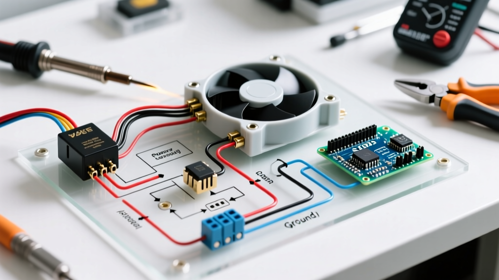
The safest and most robust wiring diagram for rear view camera installations utilizes a 12V automotive relay. This method uses the vehicle's reverse light only as a low-current 'trigger' signal, while the camera draws its actual operating current directly from the battery or a dedicated 12V accessory fuse.
Expert Insight: Never power a camera directly from the reverse light bulb on vehicles with LED taillights. LED circuits often use PWM to simulate resistance. Always use a relay to isolate the camera's power draw from the vehicle's sensitive CAN bus network.
Component Bill of Materials (BOM) & Sizing
To execute this isolated wiring diagram, source the following specific components. Expect a total BOM cost of approximately $25 to $35.
- Relay: Bosch 0332014150 (12V, 30A, 4-Pin Mini ISO). Cost: ~$7.00. Overkill for amperage, but provides standard pinouts and robust internal contacts.
- Inline Fuse Holder & Fuse: Bussmann HHM-A (ATM fuse holder) with a Littelfuse 0287002.PXCN (2A ATM Mini Fuse). Cost: ~$6.00. Refer to Eaton Bussmann fuse selection standards to ensure you never over-fuse a low-draw circuit.
- Wire: 16 AWG GXL Copper Wire (Primary lead) and 18 AWG GXL (Trigger lead). Cost: ~$0.45/ft.
- Connectors: Posi-Tap (PAT202) for the reverse light trigger, and Raychem DR-25 heat shrink for all battery/fuse connections.
Wire Gauge vs. Run Length Matrix
Voltage drop is the silent killer of automotive video equipment. A standard rear view camera requires a minimum of 11.5V to operate the CMOS sensor without introducing static or rolling bars. Use this matrix to select the correct wire gauge based on the total round-trip distance from the front power source to the rear camera.
| Total Wire Run (Round Trip) | Camera Draw (Typical) | Required Wire Gauge (GXL) | Expected Voltage Drop |
|---|---|---|---|
| Under 10 Feet | 0.3A - 0.5A | 18 AWG | < 0.10V |
| 10 to 25 Feet (Sedans/Coupes) | 0.3A - 0.5A | 16 AWG | 0.15V - 0.25V |
| 25 to 45 Feet (SUVs/Trucks) | 0.3A - 0.8A | 14 AWG | 0.30V - 0.45V |
| 45+ Feet (RVs/Trailers) | 0.5A - 1.2A | 12 AWG | < 0.50V |
Step-by-Step Execution: Reverse Light Trigger Isolation
Step 1: The Trigger Tap (POS-TAP vs. Solder)
Locate the reverse light positive wire at the taillight harness. Strip back a 1/2 inch section of the wire's insulation without cutting the copper strands. Insert the main wire into the U-shaped channel of a Posi-Tap connector and twist the cap down until it clicks. This design clamps the wire without severing strands. Run an 18 AWG trigger wire from the Posi-Tap to the firewall or cabin where your relay will be mounted.
Step 2: Relay Wiring & Fuse Placement
Mount the 4-pin relay in a dry, protected area (e.g., behind the kick panel or under the dash). Wire the relay as follows:
- Pin 86 (Coil +): Connect to the 18 AWG trigger wire from the reverse light.
- Pin 85 (Coil -): Connect to a clean, bare-metal chassis ground.
- Pin 30 (Switch Input): Connect to a dedicated 12V source (e.g., an accessory fuse tap in the cabin fuse box) via the 2A inline ATM fuse. Crucial: The fuse must be within 6 inches of the power source.
- Pin 87 (Switch Output): Connect to the 16 AWG primary power wire running to the rear of the vehicle.
Step 3: Camera Power & Grounding
Route the 16 AWG wire through the vehicle's rubber grommets into the trunk or tailgate. Connect this wire to the red power lead on the camera's RCA/Power pigtail. Ground the camera's black wire directly to a factory chassis bolt in the tailgate. Do not ground the camera to the taillight housing; this creates a ground loop, resulting in alternator whine or horizontal scrolling bars on your head unit display.
Edge Cases & Failure Mode Analysis
Even with a perfect wiring diagram for rear view camera setups, modern vehicles present unique edge cases. Here is how to troubleshoot them:
- CAN Bus 'Bulb Out' Warning: If your vehicle uses a BCM to monitor reverse light current, the Posi-Tap trigger might draw enough micro-current to confuse the module, or the removal of an incandescent bulb for an LED swap might trigger a dash warning. Fix: Install a 10W 10-ohm load resistor in parallel with the reverse light circuit, or use a dedicated CAN bus error-canceling trigger module (e.g., PAC TR-4).
- Camera Flickering on Engine Start: Alternator ripple voltage can exceed 14.8V during cold cranking, causing the camera's internal voltage regulator to reset. Fix: Add a 1000µF electrolytic capacitor across the 12V and Ground wires at the camera's pigtail to act as a buffer.
- Horizontal Scrolling Bars (Ground Loop): Caused by differing ground potentials between the head unit and the tailgate. Fix: Install a PAC SNI-35 RCA ground loop isolator on the video cable near the head unit.
Frequently Asked Questions
Can I use a fuse tap on the reverse light fuse in the cabin fuse box instead of tapping the wire at the tailgate?
Yes, this is often preferred on modern vehicles with complex rear lighting modules. However, you must ensure the fuse tap is inserted in the correct direction (load side vs. source side) to avoid back-feeding current through the fuse block, which can melt the plastic housing. Always test with a multimeter to verify the 'hot' side of the fuse slot before inserting the add-a-circuit tap.
Why did my camera work for a month and then die?
Corrosion at the ground point or an undersized wire gauge causing thermal degradation. If you used standard 18 AWG PVC wire on a 30-foot run, the voltage drop likely forced the camera's internal regulator to overheat and fail prematurely. Always use GXL wire and adhere to the voltage drop matrix above.
Is it safe to wire the camera to a constant 12V source so it acts as a dashcam when parked?
No. Standard CMOS backup cameras are not rated for continuous thermal duty cycles and will overheat if left on for hours. Furthermore, wiring to a constant 12V source without a low-voltage cutoff module will drain your vehicle's battery below the threshold required to start the engine. Stick to the ignition-switched or reverse-triggered relay diagram for safety and battery preservation.