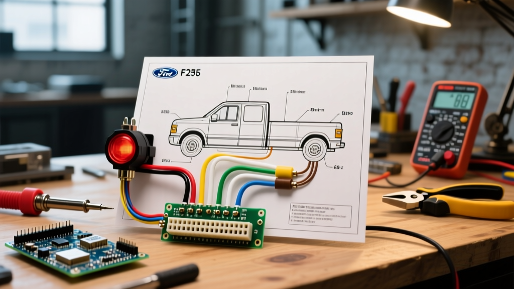

Understanding the 7-Pin RV Blade Connector on the F-250
The Ford F-250 Super Duty is an industry standard for heavy towing, frequently equipped from the factory with the 7-way RV blade connector. Whether you are pulling a horse trailer, a fifth-wheel RV, or a flatbed equipment trailer, understanding the exact pinout and electrical behavior of this connector is critical for safety and DOT compliance. When searching for a 7 pin Ford F250 wiring diagram for trailer lights, most DIYers overlook the complex integration of the truck's Trailer Tow Module (TTM), which actively monitors circuits and alters power delivery compared to older, hardwired systems.
This comprehensive guide breaks down the exact pinout, wire color standards, Pulse Width Modulation (PWM) quirks specific to modern F-250s, and the precise fuse locations for the 2020-2026 Super Duty generations.
Ford F-250 7-Pin Wiring Diagram & Pinout Chart
The physical 7-pin connector on the F-250 follows the standardized RVIA (Recreation Vehicle Industry Association) blade layout. Below is the universal pinout for the trailer side plug, which mates directly with the F-250's factory receptacle.
| Pin Position | Function | Standard Trailer Wire Color | Wire Gauge (Min) |
|---|---|---|---|
| 1 (11 o'clock) | Ground (Chassis) | White | 10 AWG |
| 2 (1 o'clock) | 12V Aux / Battery Charge | Black | 10 AWG |
| 3 (3 o'clock) | Right Turn / Stop | Green | 16 AWG |
| 4 (9 o'clock) | Left Turn / Stop | Yellow | 16 AWG |
| 5 (5 o'clock) | Tail / Running Lights | Brown | 16 AWG |
| 6 (7 o'clock) | Electric Trailer Brakes | Blue | 12 AWG |
| 7 (Center) | Reverse / Aux | Purple | 14 AWG |
The PWM Tail Light Issue: A Modern F-250 Quirk
Expert Warning: If your modern LED trailer lights flicker, strobe, or fail to illuminate when plugged into a newer F-250, your wiring is likely fine. You are experiencing a PWM mismatch.
Starting with the 2017 generation and continuing through the current 2026 models, Ford utilizes a Smart Trailer Tow Module (TTM). To detect blown bulbs on the trailer, the TTM sends a Pulse Width Modulation (PWM) signal down the Brown (Tail/Running Light) wire rather than a steady 12V DC current. Standard incandescent bulbs ignore this rapid pulsing and glow steadily. However, modern all-LED trailer lights interpret the PWM signal as rapid on/off switching, resulting in severe flickering or total failure to turn on.
The Fix: You do not need to rewire the truck. Install a PWM-to-DC converter module (such as the CURT 57003 or a dedicated LED trailer adapter) between the truck's 7-pin receptacle and the trailer's junction box. This smooths the PWM signal into a steady 12V DC output, eliminating flicker and stopping the F-250 dashboard from throwing false 'Trailer Wiring Fault' codes.
OEM Truck Harness vs. Standard Trailer Wiring
A massive point of confusion when using a 7 pin Ford F250 wiring diagram for trailer lights is the difference between the trailer-side colors and the OEM truck-side pigtail colors. If you are replacing the truck's receptacle using an OEM replacement harness like the Tekonsha 118267 or Motorcraft WPT-1246, the wire colors under the truck's bed often differ from the standard trailer colors.
- Ground: Truck harness may use Black or White (Trailer uses White).
- 12V Aux: Truck harness often uses Orange or Black/Red (Trailer uses Black).
- Reverse: Truck harness may use Light Green or Purple (Trailer uses Purple).
Always trust the pin position on the physical connector face rather than relying solely on wire color when splicing into the F-250's chassis harness. Use a digital multimeter to verify continuity to the corresponding pin on the bumper receptacle.
Step-by-Step Diagnostic & Testing Procedure
Before tearing apart the bumper or dropping the spare tire to access the harness connector, verify the output at the receptacle using a digital multimeter (e.g., Fluke 117 or Klein Tools MM400).
- Set Multimeter to DC Voltage (20V range).
- Test Ground (Pin 1): Place the black probe on the truck chassis (bare metal) and the red probe on Pin 1. It should read near 0.00V. If it reads 12V, your ground circuit is open.
- Test 12V Aux (Pin 2): Red probe on Pin 2, black on Pin 1. Should read 12.5V - 13.8V with the ignition ON.
- Test Tail Lights (Pin 5): Turn on the F-250 parking lights. Probe Pin 5. Note the PWM reading (it may fluctuate between 4V and 12V rapidly on a standard multimeter; use a test light to confirm the circuit is active).
- Test Turn Signals (Pins 3 & 4): Activate the hazard flashers. Probe Pins 3 and 4. You should see a pulsing 12V signal alternating with 0V.
- Test Electric Brakes (Pin 6): With the ignition ON, manually slide the Integrated Trailer Brake Controller (ITBC) slider on the F-250 dashboard. Pin 6 should read 12V at maximum gain.
Common F-250 Super Duty Wiring Failure Modes
When troubleshooting trailer light failures on the 2020-2026 F-250 Super Duty, the issue is rarely a broken wire in the harness. It is almost always a blown fuse in the Battery Junction Box (BJB) or a software lockout by the TTM.
1. Blown BJB Fuses
The Under-Hood Battery Junction Box contains high-amperage fuses dedicated to the 7-pin connector. Common culprits include:
- Fuse 61 (30A): Protects the Trailer Brake Controller power. If your trailer brakes are dead but lights work, check this first.
- Fuse 89 (40A): Protects the 12V Aux (Charge) circuit. Essential for charging RV house batteries or powering trailer jacks.
- Fuse 90 (30A): Main power feed for the Trailer Tow Module (TTM).
Note: Always verify exact fuse locations using your specific model year's owner manual, as Ford occasionally revises BJB layouts between production runs.
2. TTM Software Lockout
The F-250's TTM is highly sensitive to short circuits. If a trailer wire shorts to ground (common in frayed 4-flat adapter pigtails), the TTM will instantly cut power to that specific circuit to protect the truck's CAN bus network. Replacing the fuse will not fix the issue. You must clear the fault by disconnecting the trailer, turning the truck OFF, opening and closing the driver's door to put the TTM to sleep, and then restarting the truck.
3. Receptacle Corrosion
The F-250's 7-pin socket is exposed to road salt and debris. Galvanic corrosion between the brass pins and the aluminum/copper wiring causes voltage drops, leading to dim trailer lights or weak brake controller output. Apply Permatex Dielectric Tune-Up Grease to the pins every 6 months, and consider upgrading to a sealed, marine-grade receptacle like the Pro Series 63085 if you tow in harsh winter conditions.
Recommended Upgrades & Maintenance for 2026 Towing
To ensure maximum reliability and safety, adhere to the lighting and wiring standards outlined by the FMCSA in 49 CFR Part 393, which mandates specific visibility and circuit integrity for commercial and heavy-duty towing.
- Upgrade to a Heavy-Duty Socket: The OEM Ford socket can become loose over time, causing the heavy trailer plug to sag and lose contact with the top pins (Ground and 12V Aux). Replace it with a CURT 55774 7-pin socket with a stainless steel spring-loaded flap.
- Install a Wireless Monitoring System: Devices like the CURT BetterWeigh or the Garmin BC 50 wireless camera systems plug directly into the 7-pin and provide real-time diagnostics of your trailer's lighting circuits directly to your smartphone or head unit.
- Use Proper Adapters: If you frequently switch between a 7-pin RV blade and a 4-flat utility trailer, avoid cheap, dangling adapter cords. Install a flush-mounted Hopkins 40924 dual-output connector that houses both a 7-pin and a 4-flat in the same bumper bezel, eliminating the need for adapters that drag on the asphalt.
Frequently Asked Questions
Why does my F-250 dashboard say 'Check Trailer Wiring' when the lights work?
This is almost always caused by the TTM detecting an unexpected current draw on the tail light circuit (Pin 5). If you recently upgraded your trailer to LED lights, the low amperage draw tricks the Ford module into thinking a bulb is blown. Install a PWM filter or an LED load resistor to resolve the dashboard warning.
Can I wire a 12V fridge in my trailer directly to Pin 2?
Pin 2 provides 12V Aux power, but the F-250's factory wiring is typically limited by a 40A fuse (Fuse 89). While a 12V compressor fridge draws roughly 10-15 amps, voltage drop over a 25-foot trailer harness can cause the fridge to underperform or trigger the TTM's overcurrent protection. For high-draw appliances, run a dedicated 10 AWG power line from an auxiliary battery setup or install a heavy-duty DC-DC charger in the trailer.
Does the Ford Integrated Brake Controller use Pin 6?
Yes. The F-250's factory Integrated Trailer Brake Controller (ITBC) sends the PWM brake signal directly to Pin 6 (Blue wire). If you are using an aftermarket brake controller (like the Tekonsha Prodigy P3), you must splice into the Blue wire under the dash rather than the bumper, bypassing the factory ITM module entirely to prevent signal conflicts.
For further technical specifications regarding factory towing configurations, always refer to the official Ford Motor Company Towing Guides and consult the etrailer.com Wiring and Connector FAQ for vehicle-specific harness replacement part numbers.