
The Anatomy of a 7-Way RV Blade Connector
When building, repairing, or upgrading a trailer harness, referencing a precise trailer electrical connector wiring diagram is only half the battle. The most common cause of trailer electrical failure—ranging from dim running lights to catastrophic electric brake fade—is the improper selection of wire gauge (AWG) for specific circuits. While the Recreation Vehicle Industry Association (RVIA) and the Society of Automotive Engineers (SAE) dictate standard color codes, they do not strictly police the copper cross-section used in aftermarket replacement pigtails. Many cheap, off-the-shelf 7-way molded connectors utilize undersized 16 AWG wire for all seven pins to save manufacturing costs, leading to severe voltage drop over a 25-foot trailer tongue.
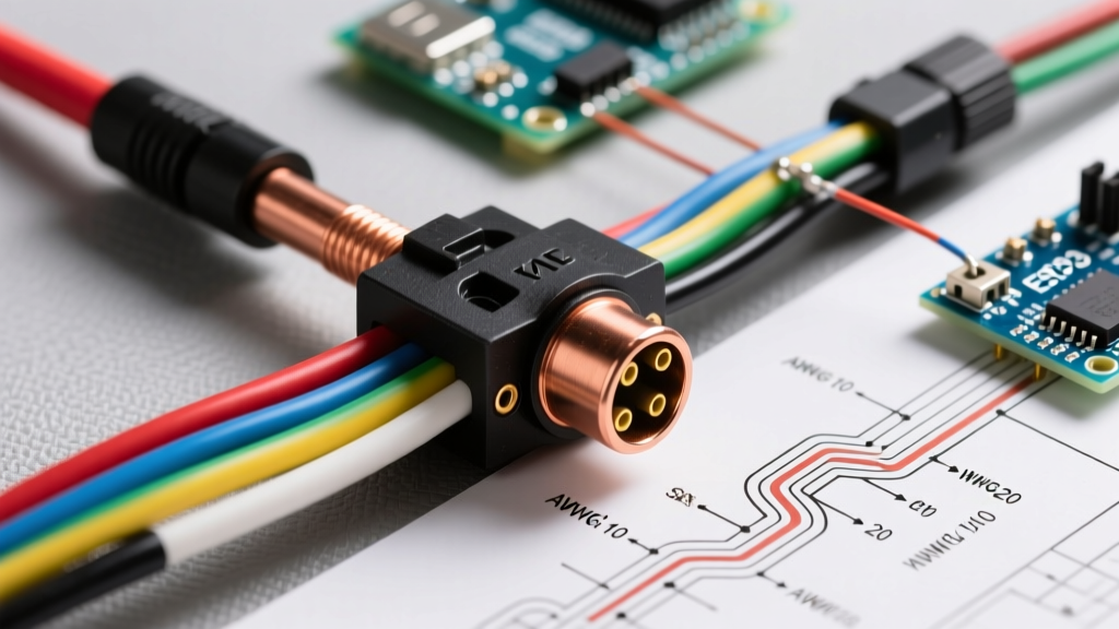
Below is the definitive matrix for a standard 7-way RV blade connector, combining the universally accepted SAE/RVIA color codes with the minimum recommended American Wire Gauge (AWG) for safe, high-performance operation.
| Pin Position | Function | SAE Color Code | Min. AWG | Max Continuous Load |
|---|---|---|---|---|
| 1 (Ground) | Chassis Ground Return | White | 10 AWG | 30A |
| 2 | Tail / Running Lights | Brown | 14 AWG | 15A |
| 3 | Left Turn / Stop Lamp | Yellow | 14 AWG | 15A |
| 4 | Right Turn / Stop Lamp | Green | 14 AWG | 15A |
| 5 | Electric Trailer Brakes | Blue | 10 AWG | 30A |
| 6 | 12V Auxiliary / Battery Charge | Black | 10 AWG | 30A |
| 7 | Reverse Lamps / Aux Power | Purple | 14 AWG | 15A |
Wire Gauge Selection: Why AWG Matters in Trailer Wiring
Wire gauge determines the electrical resistance of the conductor. In a 12V DC system, resistance causes voltage drop, which manifests as heat in the wire and reduced power at the load. According to the National Electrical Code (NEC) Chapter 9, Table 8, stranded 10 AWG copper wire has a resistance of approximately 1.24 ohms per 1,000 feet at 75°C. In contrast, 16 AWG wire has a resistance of 4.99 ohms per 1,000 feet. If you use 16 AWG wire for an electric brake circuit pulling 12 amps over a 30-foot run (60 feet total round-trip), you will lose nearly 3.6 volts before the current ever reaches the brake magnets. This leaves your brakes operating at roughly 70% capacity, a dangerous failure mode on steep downgrades.
The Electric Brake Circuit: A Critical Load
Modern electric trailer brakes, such as the Dexter Nev-R-Adjust or Lippert self-adjusting assemblies, typically draw between 3.0 and 3.5 amps per wheel under full controller output. A dual-axle (4-wheel) trailer will pull 12 to 14 amps continuously when the brake controller (e.g., Tekonsha Prodigy P3 or Redarc Tow-Pro Elite) commands maximum output.
- 10 AWG Blue Wire: Mandatory for dual and triple-axle trailers to ensure the brake magnets receive a full 12V, providing immediate and proportional stopping power.
- 12 AWG Blue Wire: Acceptable only for single-axle trailers (2 brakes, ~7A total draw) where the cable run from the tow vehicle alternator to the trailer axles is under 20 feet.
Calculating Voltage Drop for Long Trailers
For gooseneck, fifth-wheel, or extended car haulers, the distance from the tow vehicle's 7-way receptacle to the trailer's rear lighting and axles can exceed 50 feet. To comply with federal lighting intensity mandates outlined in FMVSS 108 (Federal Motor Vehicle Safety Standard No. 108), your tail and stop lamps must receive adequate voltage to achieve minimum candela ratings.
Voltage Drop Formula (DC):
VD = 2 × L × R × I
Where L = one-way length in thousands of feet, R = wire resistance per 1,000 ft, and I = current in amps.
Real-World Scenario: You are wiring the running lights (Brown wire) on a 40-foot car hauler using 14 AWG wire (resistance ~3.14 ohms/kft). The LED marker and tail lights draw a combined 4 amps.
VD = 2 × 0.040 × 3.14 × 4 = 1.00 Volt Drop.
Your rear lights will receive 11.0V instead of 12.0V. While acceptable for LEDs, if you upgrade the trailer to draw 10 amps using incandescent bulbs, the drop becomes 2.51 volts, leaving only 9.49V at the socket—resulting in noticeably dim lights and potential hyper-flashing of the tow vehicle's turn signals.
4-Way, 5-Way, and 6-Way Connector Variations
Not all trailers require a 7-way blade. Smaller utility, boat, and motorcycle trailers utilize simpler connectors. The color codes remain largely consistent, but the gauge requirements shift based on the absence of high-draw circuits.
- 4-Way Flat: Used for basic lighting (Ground, Tail, Left, Right). Since there are no electric brakes, 16 AWG is often sufficient for short trailers, but 14 AWG is highly recommended for any trailer exceeding 15 feet to prevent voltage drop on the tail light circuit.
- 5-Way Flat: Adds a Blue wire for surge brake solenoids (common on boat trailers). The solenoid draws minimal current (usually under 2A) just to lock out the reverse mechanism, so 14 AWG for the blue wire is perfectly adequate.
- 6-Way Round / Square: Common on horse and livestock trailers. Pinouts vary wildly between manufacturers (some place the 12V aux on the center pin, others place the ground there). Always test the tow vehicle receptacle with a multimeter or circuit tester before wiring the trailer side.
Edge Cases and Common Failure Modes
The Ground Loop Fallacy
Many DIYers assume the steel trailer ball and coupler provide an adequate ground path. This is a critical error. The hitch ball is subject to grease, paint, rust, and kinetic bouncing, all of which introduce massive electrical resistance. The White ground wire (Pin 1) must be heavily sized (10 AWG or even 8 AWG for large toy haulers) and bonded directly to the bare, sanded metal of the trailer chassis near the tongue. Failure to do so results in "ground loops," where current seeks an alternate path to ground—often backfeeding through the license plate light or brake light filaments, causing lights to flicker or behave erratically when the turn signal is engaged.
LED Upgrades and Hyper-Flashing
Upgrading a trailer from incandescent to LED lighting reduces the amp draw from ~4A per circuit to less than 0.5A. While this virtually eliminates voltage drop, it starves the tow vehicle's thermal flasher relay of the load it needs to cycle properly, causing hyper-flashing. The solution is not to add inline resistors (which generate excessive heat and defeat the purpose of LEDs), but to install a solid-state, LED-compatible flasher relay in the tow vehicle's fuse panel, or use a dedicated trailer wiring converter module (like the Tekonsha 119190 ModuLite) that draws power directly from the tow vehicle's battery rather than the taillight circuits.
Pro-Termination and Weatherproofing Standards
A perfect wiring diagram is useless if the terminations corrode within a year. Trailer connectors operate in harsh environments, exposed to road salt, water immersion (boat ramps), and extreme vibration.
- Adhesive-Lined Heat Shrink: Never use standard vinyl electrical tape or non-adhesive heat shrink. Use dual-wall, adhesive-lined polyolefin heat shrink (e.g., 3M MDT series). When heated, the inner thermoplastic adhesive melts and seals the wire strands, creating a 100% waterproof barrier against capillary action.
- Dielectric Grease: Apply a high-quality silicone dielectric grease (such as Permatex 22058) to all 7-way blade pins and socket cavities. This displaces moisture and prevents galvanic corrosion between the brass pins and the copper wire.
- Strain Relief: The transition point where the thick 7-way molded cable enters the trailer frame is the highest failure point for copper strand fatigue. Always use a rubber grommet and secure the cable with a P-clamp within 3 inches of the entry hole to prevent vibration-induced wire breakage inside the insulation.
Frequently Asked Questions (FAQ)
Can I use 16 AWG wire for the entire 7-way harness?
No. While 16 AWG can handle the low current of LED marker lights, using it for the 12V auxiliary (Black) or Electric Brake (Blue) circuits will cause severe voltage drop and overheating. Always step up to 10 AWG for high-draw and ground circuits.
Why do my trailer running lights dim when I hit the brakes?
This is a classic symptom of a poor ground connection or undersized ground wire. When the high-draw brake lights (or electric brakes) engage, the current cannot return efficiently through the White ground wire, so it backfeeds through the Brown running light circuit, stealing voltage from the tail lamps.
What wire type is best for trailer chassis routing?
Avoid standard PVC-jacketed wire (like THHN) for exterior chassis routing, as it degrades under UV exposure and road debris impacts. Use GXL or SXL (cross-linked polyethylene) automotive wire. GXL features a thin wall, allowing you to route more conductors through tight frame channels while offering superior abrasion and heat resistance. For ultimate protection, route the entire harness through split corrugated loom secured with UV-resistant zip ties or aluminum P-clamps.