
Understanding the Standard Wiring Diagram for Trailer Hitch Setups
Whether you are hauling a small utility trailer or a heavy-duty travel RV, interpreting the correct wiring diagram for trailer hitch connections is non-negotiable for safety and legal compliance. In the United States, trailer lighting circuits are governed by Federal Motor Vehicle Safety Standard (FMVSS) 108 and SAE J286 specifications. A miswired harness doesn't just blow fuses; it can cause erratic electric brake behavior or blind the drivers behind you.
This comprehensive reference guide breaks down the exact pinouts, wire color standards, gauge requirements, and diagnostic procedures for the two most common consumer connectors: the 4-way flat and the 7-way RV blade. We will also cover the hidden electrical pitfalls—like voltage drop and ground loops—that cause 80% of all trailer lighting failures.
4-Way Flat Connector: Pinout and Wire Color Standards
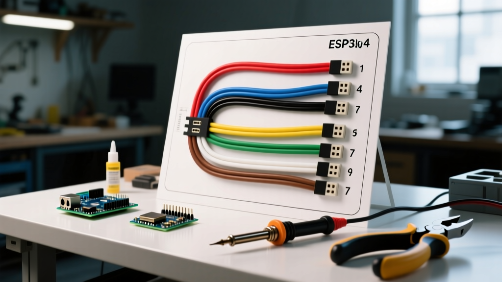
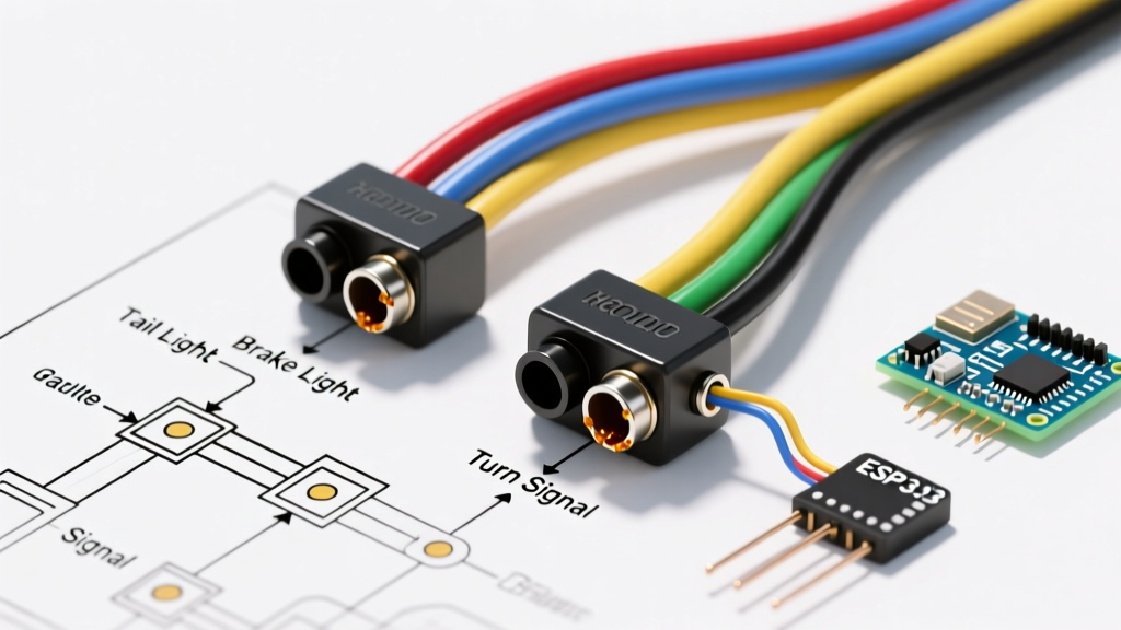
The 4-way flat connector is the industry standard for light-duty trailers (under 3,000 lbs Gross Vehicle Weight Rating) that do not require electric brakes or auxiliary power. It handles the absolute minimum legal lighting requirements: running lights, left turn/stop, right turn/stop, and ground.
4-Pin Flat Wiring Matrix
| Pin Position (Vehicle Side) | Function | Standard Wire Color | Recommended Min. Gauge |
|---|---|---|---|
| Pin 1 (Leftmost / Ground Tab) | Chassis Ground | White | 16 AWG (12 AWG preferred) |
| Pin 2 | Tail / Running Lights | Brown | 16 AWG |
| Pin 3 | Left Turn & Stop Lights | Yellow | 16 AWG |
| Pin 4 (Rightmost) | Right Turn & Stop Lights | Green | 16 AWG |
Expert Insight: Most off-the-shelf 4-pin harness kits (like the Tow Ready 118149) use 18 AWG wire to save costs. If your trailer exceeds 20 feet in length, the resistance in 18 AWG wire will cause severe voltage drop, resulting in dim tail lights and hyper-flashing turn signals. Always upgrade the main run to 14 AWG or 12 AWG for long trailers.
7-Way Blade Connector: Advanced Towing and Brake Circuits
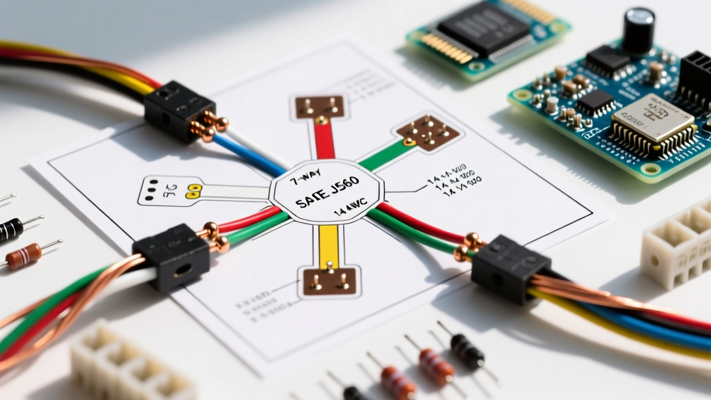
For travel trailers, horse trailers, and heavy equipment haulers, the 7-way RV blade connector (SAE J286) is mandatory. It adds three critical circuits to the standard 4-way setup: electric brakes, 12V auxiliary power (for charging breakaway batteries or interior lights), and a reverse/auxiliary circuit.
7-Pin RV Blade Wiring Matrix
When looking at the vehicle-side socket (female), the pins are arranged in a specific clock-face pattern. Note that commercial 7-way round connectors use a completely different pinout; the chart below applies strictly to the consumer RV blade.
| Pin / Clock Position | Function | Standard Wire Color | Circuit Load / Notes |
|---|---|---|---|
| Pin 1 (7 o'clock) | Chassis Ground | White | Must handle total amperage of all lights + brakes. Use 10 AWG. |
| Pin 2 (3 o'clock) | Electric Brakes | Blue | Connects to brake controller (e.g., Tekonsha Prodigy P3). 12 AWG min. |
| Pin 3 (5 o'clock) | Tail / Running Lights | Brown | 14 AWG recommended for multi-marker light setups. |
| Pin 4 (1 o'clock) | 12V Auxiliary Power | Black | Hot at all times. Used for breakaway battery charging. 12 AWG. |
| Pin 5 (9 o'clock) | Right Turn & Stop | Green | 16 AWG minimum. |
| Pin 6 (11 o'clock) | Left Turn & Stop | Yellow | 16 AWG minimum. |
| Pin 7 (Center) | Reverse Lights / Aux | Purple | Often used for reverse lockout solenoids on surge brakes. |
The Hidden Culprit: Grounding and Voltage Drop Calculations
The most common reason a trailer wiring setup fails is not a broken wire, but a poor ground. Trailer hitches rely on the physical ball-and-coupler connection to complete the ground circuit. If the hitch ball is painted, rusted, or coated in grease, the electrical current will seek an alternative path, often backfeeding through the tail light circuit. This results in the classic 'ghosting' symptom: hitting the brakes causes the running lights to illuminate dimly.
Calculating Voltage Drop for Long Trailers
According to standard electrical engineering principles, a voltage drop exceeding 3% is unacceptable for automotive lighting. You can calculate the voltage drop using the following formula:
Voltage Drop (Vd) = (2 × L × I × R) / 1000
- L = One-way length of the wire in feet
- I = Current draw in Amps
- R = Resistance of the wire per 1,000 feet (e.g., 16 AWG is ~4.016 ohms/kft; 12 AWG is ~1.588 ohms/kft)
Real-World Scenario: A 25-foot trailer with 8 LED marker lights and 4 tail lights drawing a combined 4 Amps on the brown (running light) wire. Using standard 16 AWG wire (50 ft total round trip), the voltage drop is roughly 1.6V. On a 12V system, that leaves only 10.4V at the furthest marker light, which may cause LEDs to flicker or fail to trigger. Upgrading to 12 AWG reduces the drop to 0.63V, ensuring a solid 11.37V delivery.
Step-by-Step Multimeter Diagnostic Flow
When your trailer lights malfunction, skip the guesswork and use a Digital Multimeter (DMM) to isolate the fault. Follow this exact sequence:
- Verify the Vehicle Socket: Unplug the trailer. Turn on the tow vehicle's running lights. Set your DMM to DC Voltage (20V range). Place the black probe on the vehicle's white ground pin and the red probe on the brown pin. You should read 12.2V to 12.6V. If you read 0V, the issue is in the tow vehicle's harness or fuse box.
- Test the Ground Continuity: With the trailer disconnected, set the DMM to Continuity/Ohms. Place one probe on the trailer plug's white pin and the other on a bare metal part of the trailer frame. A reading of less than 1.0 ohm indicates a solid ground. If it reads 'OL' (Open Loop), your trailer frame ground wire is corroded or detached.
- Check for Backfeed (Shorts): If your turn signals illuminate the running lights, you have a short. Disconnect the trailer. Probe the vehicle socket's yellow pin (left turn) while an assistant presses the brake/turn signal. If voltage appears on the adjacent brown pin, the vehicle-side converter module (common in modern multiplexed wiring systems like the Curt 56282) has failed internally.
4-Pin to 7-Pin Adapter Internal Logic
Many DIYers use a 4-way to 7-way adapter (like the Hopkins 47185) when towing a trailer with electric brakes using a vehicle that only has a 4-pin flat. It is critical to understand that an adapter does not magically create brake or auxiliary circuits.
Inside the adapter, the white, brown, yellow, and green wires simply pass straight through. The blue (brake) and black (12V aux) wires on the 7-way side are left as open pigtail wires. You must manually route the blue wire through the firewall to an aftermarket brake controller, and connect the black wire directly to the vehicle's battery via a 30A inline circuit breaker. Failing to wire these pigtails means your trailer's electric brakes will remain completely inactive, creating a severe safety hazard on downgrades.
Maintenance and Corrosion Prevention
Trailer connectors live in the harshest environment on your vehicle—exposed to road salt, water, and constant vibration. To ensure the longevity of your wiring diagram implementation:
- Dielectric Grease: Apply a marine-grade dielectric grease (such as Permatex 22058) to the pins of both the male and female connectors before mating them. This displaces moisture and prevents galvanic corrosion between the brass pins and copper wire.
- Heat Shrink over Electrical Tape: Never use standard vinyl electrical tape for outdoor trailer splices. The adhesive degrades in UV light and heat. Always use adhesive-lined marine heat shrink tubing (e.g., 3M MFP) which melts an inner sealant around the wire, creating a waterproof barrier.
- Spray Contacts: Once a year, spray the vehicle socket with an electrical contact cleaner to remove oxidized brass dust that increases resistance.
For deeper regulatory context on commercial and heavy-duty lighting requirements, refer to the FMCSA Title 49 Part 393 guidelines. Additionally, manufacturer-specific harness routing diagrams can be found via CURT Manufacturing Wiring Support.
Frequently Asked Questions
Why do my trailer lights work when plugged into the truck, but blow the fuse when I hit the brakes?
This is almost always caused by a short to ground in the trailer's stop/turn circuit. When you hit the brakes, the current surges. If the yellow or green wire has a frayed section touching the metal trailer frame, it will immediately draw maximum amperage and blow the tow vehicle's fuse. Inspect the wiring near the trailer tongue hinge, where wires are frequently pinched.
Can I use a 5-way flat connector instead of a 4-way?
Yes. A 5-way flat connector uses the exact same pinout as the 4-way flat for the first four pins, adding a fifth pin (usually blue) specifically for a reverse lockout solenoid on surge brake systems. A 5-way trailer can be safely plugged into a 4-way vehicle socket; the fifth pin will simply hang unused, and the standard lights will function perfectly.