
Translating an Arduino Wiring Diagram to Physical Reality
Downloading a clean, colorful Arduino wiring diagram from Fritzing or Tinkercad is only the first step in building a reliable microcontroller project. While these schematics perfectly illustrate logical connections, they rarely specify the physical wire gauge or insulation color required for real-world deployment. Relying on a random assortment of 28 AWG breadboard jumper wires for a project that draws significant current is a primary cause of voltage drops, erratic sensor readings, and in extreme cases, melted insulation or fried voltage regulators.
As makers and engineers transition from prototype to permanent installation, understanding the relationship between wire gauge, current capacity, and standardized color coding becomes critical. This guide bridges the gap between theoretical schematics and physical wiring harnesses, ensuring your Arduino-based projects are both electrically sound and easy to troubleshoot.
Decoding the Schematic: Signal Paths vs. Power Paths
When analyzing any Arduino wiring diagram, you must mentally separate the circuit into two distinct domains: signal paths and power paths. Treating them identically is a common beginner mistake.
Signal Paths (Logic Level)
Signal paths carry data or logic states. Examples include I2C buses (SDA/SCL), SPI lines (MOSI, MISO, SCK), analog sensor outputs, and standard digital I/O pins. These paths carry negligible current—typically under 20mA. The primary concern here is not current capacity, but rather capacitance and interference. Long, unshielded, or improperly gauged signal wires can act as antennas, picking up electromagnetic interference (EMI) and causing ghost triggers or communication NACK errors.
Power Paths (Current Delivery)
Power paths deliver the energy required to drive actuators, displays, and lighting. This includes wiring for NEMA 17 stepper motors, high-torque servos, NeoPixel LED strips, and heating elements. According to the official Arduino Uno Rev3 documentation, the onboard 5V regulator can safely supply only about 500mA to 800mA depending on thermal conditions. Therefore, power paths for high-draw components must bypass the Arduino board entirely, drawing directly from an external power supply, which necessitates thicker wire gauges.
Wire Gauge Selection Matrix for Arduino Projects
Selecting the correct American Wire Gauge (AWG) is a balance between current capacity, physical flexibility, and breadboard compatibility. The following matrix provides specific guidelines for common Arduino applications. For deeper electrical engineering standards on ampacity, refer to the Engineering Toolbox AWG Wire Gauge Chart.
| AWG Size | Max Current (Chassis) | Wire Type | Typical Arduino Application |
|---|---|---|---|
| 28 - 26 AWG | 0.5A - 1.0A | Solid Core / Dupont | Breadboard jumpers, low-current logic signals, I2C/SPI buses. |
| 24 - 22 AWG | 2.0A - 5.0A | Stranded Silicone | Sensor power rails, micro servos (SG90), standard prototyping. |
| 20 - 18 AWG | 7.0A - 10.0A | Stranded PVC/Silicone | WS2812B LED strips, NEMA 17 stepper motors, DC barrel jack inputs. |
| 16 - 14 AWG | 15.0A - 20.0A | Stranded Copper | Main battery bank feeds, high-power motor drivers (e.g., BTS7960). |
Pro Tip: For permanent installations, avoid solid core wire for power paths. Vibration and thermal cycling will cause solid core wire to work-hardened and snap. Use stranded silicone wire (typically priced around $18 to $25 for a 100ft spool of 22 AWG) for its high heat resistance and flexibility.
Standardizing Color Codes: Beyond the Rainbow Ribbon
Most hobbyists start with multi-colored 'rainbow' ribbon cables. While visually appealing, they make troubleshooting a nightmare. If an Arduino wiring diagram calls for a specific pin, but your physical build uses random colors, tracing a fault requires a multimeter and immense patience. Adopting a strict DC color code standard aligns your physical build with professional electrical practices.
Industry Standard DC Color Mapping:
Consistent color coding reduces troubleshooting time by up to 70% in complex harnesses. Never use black or green for positive voltage rails.
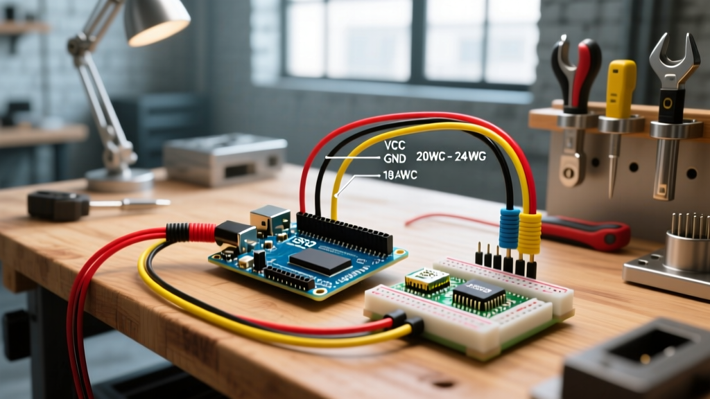
- Red: Primary Positive Voltage (e.g., 5V, 12V, 24V main rails).
- Black: System Ground (GND). All ground returns must be black.
- Yellow: Standard Digital I/O signals (e.g., relay triggers, button inputs).
- Green: I2C Data (SDA) or Analog Signals.
- Blue: I2C Clock (SCL) or specific serial lines (TX/RX).
- Orange: SPI MOSI or PWM outputs.
- Purple/Violet: SPI MISO or Chip Select (CS) lines.
- White: Signal Ground or specific sensor returns (to differentiate from main power GND).
Real-World Failure Modes: When the Wrong Gauge Burns Your Board
To understand the stakes, consider a common failure mode documented in maker communities, often referenced in guides like the Adafruit NeoPixel UberGuide.
Case Study: The Melting Jumper Wire
A builder follows an Arduino wiring diagram to control a strip of 100 WS2812B NeoPixels. The diagram shows the 5V line connecting from the Arduino's 5V pin to the LED strip's VCC. The builder uses a standard 28 AWG Dupont jumper wire. When the code commands all LEDs to turn full white, the strip attempts to draw 6 Amps (60mA x 100).
The Result: The 28 AWG wire, rated for roughly 1.4A in chassis wiring, acts as a resistor. It rapidly heats up, melting the plastic Dupont housing. Furthermore, the massive voltage drop across the thin wire starves the first few LEDs, causing them to flicker red, while the Arduino's onboard polyfuse trips or the USB trace on the PCB physically burns out. Solution: Power the LED strip directly from a 5V 10A switching power supply using 18 AWG stranded wire, and only use a 22 AWG signal wire to connect the Arduino's digital pin to the strip's DIN.
Step-by-Step: Translating a Schematic to a Physical Harness
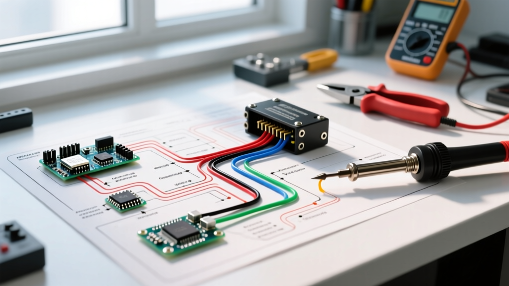
Building a reliable wiring harness requires the right tools and a methodical approach. Here is how to professionally execute your Arduino wiring diagram.
- Map and Measure: Print your schematic. Use a piece of string to measure the exact physical route the wire will take inside your enclosure. Add 15% to your measurement for slack and routing curves.
- Cut and Strip: Cut your stranded wire to length. Use a precision wire stripper (like the Hakko CHP 170 or Engineer PA-09) to strip exactly 5mm of insulation. Do not nick the copper strands, as this reduces the wire's tensile strength and current capacity.
- Crimp Ferrules: If terminating into screw terminals (common on CNC shields and relay modules), never insert bare stranded wire. It will fray and cause short circuits. Use a ferrule crimping tool (e.g., Knoweasy or IWISS SN-48B) to apply a 22 AWG or 18 AWG bootlace ferrule. Cost: roughly $12 for a comprehensive ferrule and crimper kit.
- Crimp Dupont/JST Connectors: For pin headers, use a ratcheting crimper like the IWISS SN-28B. A ratcheting mechanism ensures the crimp is fully compressed before releasing, preventing wires from pulling out under tension.
- Bundle and Sleeve: Group your wires using split loom tubing or PET expandable braided sleeving. This protects against abrasion and keeps the installation clean.
Frequently Asked Questions (FAQ)
Does wire gauge matter for I2C communication on an Arduino?
Current capacity does not matter for I2C, as it draws less than 3mA. However, wire length and capacitance do. Using extremely thin, unshielded wire over distances longer than 30cm can cause signal degradation. For long I2C runs, use 24 AWG twisted-pair cable and ensure you have 4.7kΩ pull-up resistors on both SDA and SCL lines.
Can I use copper-clad aluminum (CCA) wire for Arduino power rails?
It is highly discouraged. CCA wire has higher electrical resistance than pure copper and is brittle. In low-voltage DC systems like Arduino projects (5V or 12V), the higher resistance of CCA leads to significant voltage drops. Always purchase 100% oxygen-free copper (OFC) or standard tinned copper wire for power delivery.
How do I handle ground loops in complex Arduino wiring diagrams?
When wiring multiple high-current devices (like motors) and sensitive analog sensors, avoid daisy-chaining the ground wires. Instead, use a 'star ground' topology. Run individual ground wires (18 AWG for power, 22 AWG for signals) from each component back to a single, centralized ground bus bar or the main power supply's negative terminal. This prevents high-current return paths from inducing noise into your analog sensor readings.