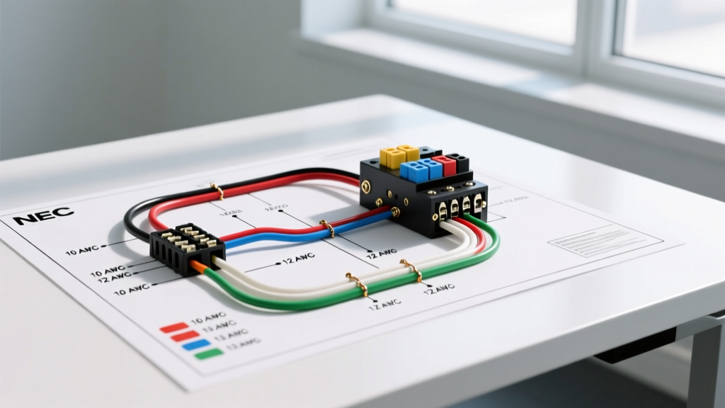

Decoding the Wiring Diagram for Transfer Switch Systems
Integrating a standby or portable generator into your home or facility's electrical system requires precision, strict adherence to the National Electrical Code (NEC), and a thorough understanding of your specific wiring diagram for transfer switch configurations. Whether you are installing an Automatic Transfer Switch (ATS) like the Generac RXSC100A3 (typically priced between $650 and $850) or a Manual Transfer Switch (MTS) such as the Reliance Controls 31410CRK ($300 to $400), the foundational principles of conductor sizing and color coding remain non-negotiable. Misinterpreting a wiring diagram can lead to catastrophic backfeeding, equipment failure, or fatal electrocution hazards.
According to the National Fire Protection Association (NFPA 70), transfer switches must completely isolate the utility supply from the generator supply. This guide breaks down the exact wire gauge requirements, NEC-mandated color codes, and critical edge cases you need to execute a flawless installation in 2026.
Utility, Generator, and Load Mapping
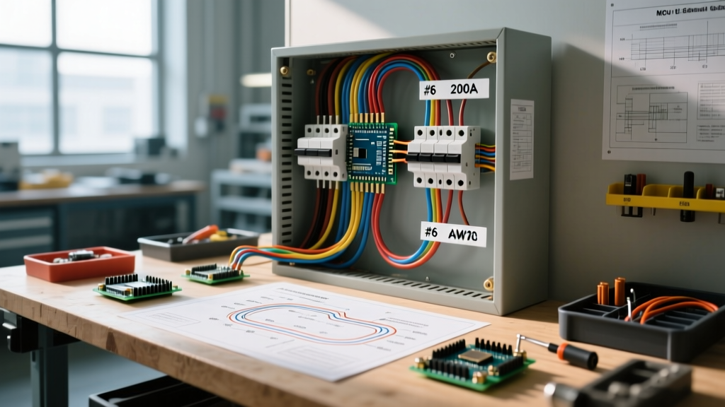
Every standard single-phase residential wiring diagram for transfer switch setups features three distinct terminal blocks: Utility (Source 1), Generator (Source 2), and Load (Distribution).
- Utility Terminals (Line 1 & Line 2): Connect directly to the main service panel's breaker via a dedicated interlock or sub-feed lug.
- Generator Terminals (Line 1 & Line 2): Connect to the generator's output receptacle (e.g., NEMA L14-30R) or hardwired ATS terminals.
- Load Terminals: Feed the designated emergency or standby sub-panel.
When reading the schematic, pay close attention to the neutral busbar. In 3-pole transfer switches, the neutral is switched alongside the hot legs. In 2-pole switches, the neutral is solidly bonded through the switch and relies on the main panel's neutral bus.
NEC-Compliant Color Codes for Transfer Switches
Color coding is not merely a suggestion; it is a strict safety requirement enforced by local inspectors and outlined by OSHA's electrical safety standards. Using the correct insulation colors prevents fatal cross-phasing and ensures maintenance personnel can instantly identify conductor functions.
Single-Phase 120/240V Split-Phase (Residential Standard)
| Conductor Function | Terminal Label | NEC Mandated Color (2026) | Common Wire Type |
|---|---|---|---|
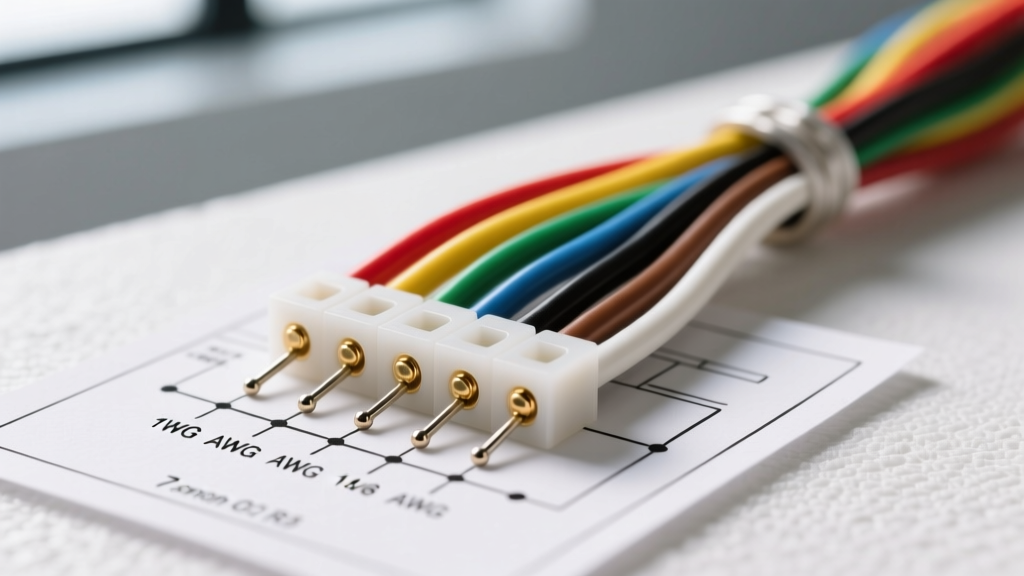
| Phase A (Hot 1) | L1 / X | Black | THHN / XHHW-2 |
| Phase B (Hot 2) | L2 / Y | Red | THHN / XHHW-2 |
| Neutral | N / W | White or Gray | THHN / XHHW-2 |
| Equipment Ground | G / EGC | Green, Green/Yellow, or Bare | Bare Copper / THHN |
Three-Phase 208Y/120V (Commercial/Light Industrial)
If your wiring diagram for transfer switch applications involves a 3-phase commercial ATS, Phase A is Brown, Phase B is Orange, Phase C is Yellow, and the Neutral is Gray. Note: Orange is specifically reserved for the high-leg (wild leg) in 240V delta systems, but in 208Y/120V systems, standard phase colors apply.
Wire Gauge Selection: Ampacity and Voltage Drop
Selecting the correct American Wire Gauge (AWG) or kcmil size is dictated by the ampere rating of the transfer switch, the overcurrent protection device (OCPD), and the physical distance between the main panel, the transfer switch, and the generator pad.
Real-World Gauge Sizing Chart (75°C Column, Copper vs. Aluminum)
Most modern transfer switch lugs (like those on Generac and ASCO models) are rated for 75°C. Always size your wire based on the 75°C column of NEC Table 310.16, regardless of the 90°C rating of THHN insulation.
| Switch Amp Rating | Min. Copper AWG | Min. Aluminum AWG | Typical SER Cable Size | Estimated Cost per Foot (2026) |
|---|---|---|---|---|
| 30A (Portable MTS) | 10 AWG | 8 AWG | 10-3 AWG w/ Grd | $1.10 - $1.40 |
| 50A (Hardwired MTS) | 6 AWG | 4 AWG | 6-3 AWG w/ Grd | $1.80 - $2.30 |
| 100A (Service Rated ATS) | 3 AWG | 1 AWG | 3-3 AWG w/ Grd | $3.50 - $4.50 |
| 200A (Whole House ATS) | 2/0 AWG | 4/0 AWG | 2/0-2/0-2/0-1/0 | $8.00 - $11.50 |
The 3% Voltage Drop Rule
FEMA's Ready.gov guidelines on power outages and generator safety emphasize that undersized wiring causes severe voltage drop, which can destroy sensitive appliance control boards (like HVAC ECM motors). For a 200-foot run from a 200A generator to an ATS, 2/0 AWG copper will yield a voltage drop of roughly 2.1% at full load, keeping you safely under the NEC recommended 3% branch/feeder limit. If using aluminum to save on material costs, you must upsize to 4/0 AWG to maintain the same voltage drop profile.
Critical Edge Case: Separately Derived vs. Non-Separately Derived Systems
The most common failure mode and code violation in transfer switch wiring is improper neutral-to-ground bonding. Your wiring diagram must explicitly address whether the system is separately derived.
⚠️ EXPERT WARNING: Neutral Bonding Conflict
If you use a 2-pole transfer switch (which does NOT switch the neutral), the utility and generator share a solid neutral path. Therefore, your portable generator's neutral MUST be bonded to its frame. If you use a 3-pole transfer switch (which switches L1, L2, and Neutral), the system becomes "separately derived." You MUST float the generator's neutral (remove the bonding screw/strap inside the generator) to prevent parallel neutral currents from traveling over the equipment grounding conductor, which will trip GFCI/AFCI breakers and create shock hazards.
Torque Specifications and Termination Best Practices
Hand-tightening lugs on a 200A transfer switch is a guaranteed way to cause a thermal failure. Aluminum and copper expand at different rates. Over time, thermal cycling causes hand-tightened connections to loosen, increasing resistance and generating immense heat.
- Tool Requirement: Use a calibrated torque screwdriver or torque wrench (e.g., Klein Tools 69500 or Wiha 60000 series).
- Typical Torque Values: Most 100A-200A mechanical lugs require between 40 in-lbs and 60 in-lbs. Always check the manufacturer's label inside the ATS enclosure.
- Oxide Inhibitor: If utilizing aluminum SER cable or aluminum THHN, you MUST apply an anti-oxidant compound (like Noalox or Penetrox E) to the stripped conductor before inserting it into the lug to prevent aluminum oxide buildup, which is highly resistive.
Frequently Asked Questions
Can I use the same wire gauge for the neutral as the hot legs?
For single-phase 120/240V residential transfer switches, yes. The NEC requires the neutral conductor to be the same size as the ungrounded (hot) conductors when serving as the primary return path for 120V loads. Never downsize the neutral in a 3-wire single-phase feeder.
Does the equipment grounding conductor (EGC) need to be switched?
No. The EGC (bare copper or green) must never pass through a switching mechanism or overcurrent device. It connects directly to the ground busbar in the transfer switch, which is bonded to the enclosure and the main service ground rod.
What conduit size do I need for 2/0 AWG THHN wires?
For a 200A ATS requiring four THHN/THWN-2 conductors (Black, Red, White, Green), NEC Chapter 9 Table 1 dictates a maximum 40% conduit fill. You will need a minimum of 1.5-inch PVC Schedule 80 or 1.5-inch EMT (Electrical Metallic Tubing) to safely pull 2/0 AWG wires without damaging the insulation.