
The Shift to Digital Schematics in the Field
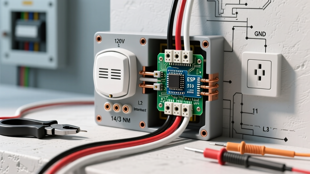
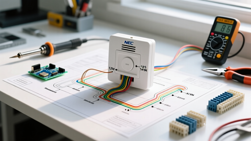
Walking up to a 400A Square D NF (NEMA Type 1) panelboard without a schematic is a recipe for misdiagnosis and potential arc flash hazards. In 2026, the industry standard for commercial and residential maintenance has decisively shifted from crumpled paper blueprints to high-resolution digital files. Having an accurate electrical panel wiring diagram PDF loaded onto a ruggedized tablet allows technicians to cross-reference physical busbars with design schematics in real-time. Whether you are tracing a ghost voltage issue, identifying an overloaded neutral, or verifying proper grounding topology, the PDF schematic is your primary troubleshooting map.
Decoding Standard Panelboard Symbols
Before tracing a fault, you must understand the nomenclature used in standard single-line and schematic diagrams. The National Fire Protection Association (NFPA 70) dictates standard symbol usage, but manufacturer-specific diagrams (like those from Eaton or Schneider Electric) often include proprietary annotations for smart breakers and metering modules.
| PDF Symbol / Annotation | Physical Component | Troubleshooting Relevance |
|---|---|---|
| CB w/ (GFPE) tag | Ground Fault Protection Equipment Breaker | Indicates a 5mA (personnel) or 30mA+ (equipment) trip threshold. Check for neutral-to-ground faults downstream. |
| Dashed Line linking poles | Common Trip / Handle Tie | Crucial for Multi-Wire Branch Circuits (MWBC). Ensures simultaneous disconnect per NEC 210.4(B). |
| N / G Bond Strap | Neutral-to-Ground Bonding Screw | Must be present in service equipment (main panel) and strictly absent in downstream subpanels. |
| CT (Donut shape) | Current Transformer | Used for energy monitoring. If a smart panel shows zero draw, verify CT orientation and wiring to the metering module. |
Step-by-Step Fault Tracing Protocol
When a specific circuit fails or exhibits anomalous behavior, use your electrical panel wiring diagram PDF to guide your physical testing sequence. Always prioritize safety and adhere to OSHA's Control of Hazardous Energy guidelines before opening panel dead-fronts.
- Isolate and LOTO: Identify the target breaker on the PDF schedule. Verify the circuit is de-energized using a CAT IV rated multimeter (e.g., Fluke 87V) via the Live-Dead-Live test method.
- Cross-Reference the Legend: Match the PDF circuit directory to the physical panel label. In older panels, directories are often inaccurate. Use a non-contact voltage detector and tone tracer to confirm the physical breaker matches the PDF designation.
- Perform Voltage Drop Testing: If the complaint is 'low voltage at the receptacle,' do not just measure at the outlet. According to Fluke Corporation's electrical testing resources, measure voltage drop across the breaker connections and the neutral busbar. A drop exceeding 3% (approx. 3.6V on a 120V circuit) indicates a high-resistance connection.
- Verify Torque Specifications: Loose connections cause thermal failure. For a standard Eaton BR 120/240V breaker, the manufacturer specifies 20 in-lbs of torque on the lug screws. Use a calibrated torque screwdriver to verify physical termination matches the engineering requirements implied by the diagram.
Common Panel Faults Revealed by PDF Schematics
Multi-Wire Branch Circuit (MWBC) Overloads
An MWBC shares a single neutral conductor between two ungrounded (hot) conductors. The electrical panel wiring diagram PDF will explicitly show the shared neutral and the phase relationships (Phase A and Phase B). If an installer mistakenly lands both hot breakers on the same busbar phase (e.g., both on Phase A), the currents do not cancel out on the neutral. Instead, they add together. A 15A load on Leg 1 and a 15A load on Leg 2 will push 30A down a #14 AWG neutral wire, creating a severe fire hazard without ever tripping the 15A breakers. The PDF allows you to verify that the breakers are physically staggered on opposite phases and tied together with an approved handle tie or common-trip breaker (e.g., Square D QO215).
Subpanel Neutral-to-Ground Bond Violations
One of the most frequent code violations found during troubleshooting is an improper neutral-to-ground bond in a subpanel. The main service disconnect requires the neutral and ground to be bonded, but downstream panels must keep them isolated.
NEC Article 250.142(B): "Grounded conductors shall not be connected to normally non-current-carrying metal parts of equipment on the load side of the service disconnecting means."
Your PDF schematic will detail the specific bonding screw or strap location. If you are troubleshooting 'tingling' shocks from appliances or stray voltage on water pipes, consult the PDF to locate the subpanel's neutral bar. Remove the dead-front and verify that the green bonding screw has been removed and that the neutral bar is floating (isolated from the metal enclosure).
2026 Digital PDF Management Best Practices
Managing schematics in the field requires more than just opening an email attachment. Modern electrical troubleshooting relies on layered digital workflows:
- Use Layered PDF Software: Applications like Bluebeam Revu or Drawboard PDF allow you to toggle layers. You can hide low-voltage control wiring layers when troubleshooting high-voltage distribution, reducing visual clutter.
- As-Built vs. Design Versions: Always ensure your tablet holds the 'As-Built' revision, not the original 'Design' PDF. Field changes during construction frequently alter breaker sizing and wire routing.
- Redlining in Real-Time: Use a stylus to redline discrepancies directly on the PDF while standing in front of the panel. Sync these markups to the cloud so the engineering team can update the master digital twin.
Quick Reference Troubleshooting Matrix
Use this matrix to quickly map field symptoms to specific checkpoints on your electrical panel wiring diagram PDF.
| Field Symptom | PDF Checkpoint | Physical Panel Test |
|---|---|---|
| Breaker trips immediately upon reset | Check for AFCI/GFCI breaker designation and shared neutral topology. | Disconnect load wires. Reset breaker. If it holds, the fault is downstream. If it trips, replace the breaker. |
| Humming or buzzing from panel enclosure | Review busbar ampacity and main breaker sizing relative to calculated loads. | Use a thermal camera to scan for hot spots on busbar stabs. Check main lug torque (typically 40-50 in-lbs for #2 AWG). |
| Flickering lights on specific circuits | Trace the circuit back to the phase it originates from on the single-line diagram. | Test voltage at the breaker output while heavy loads (like HVAC compressors) cycle on the same phase leg. |
| Smart metering module shows zero data | Verify CT (Current Transformer) wiring diagram and polarity marks (H1/X1). | Ensure CTs are facing the correct direction on the conductors and that the 12V communication harness is fully seated. |
Mastering the use of an electrical panel wiring diagram PDF transforms troubleshooting from a guessing game into a precise, data-driven science. By combining digital schematic analysis with rigorous physical testing protocols, electrical professionals can resolve complex faults safely, ensure strict NEC compliance, and minimize system downtime.