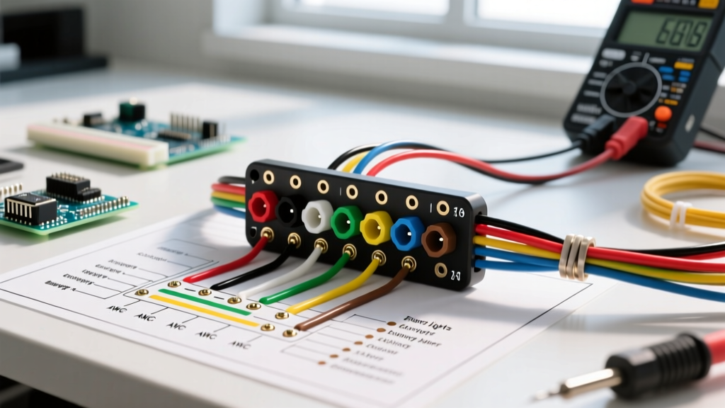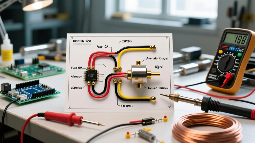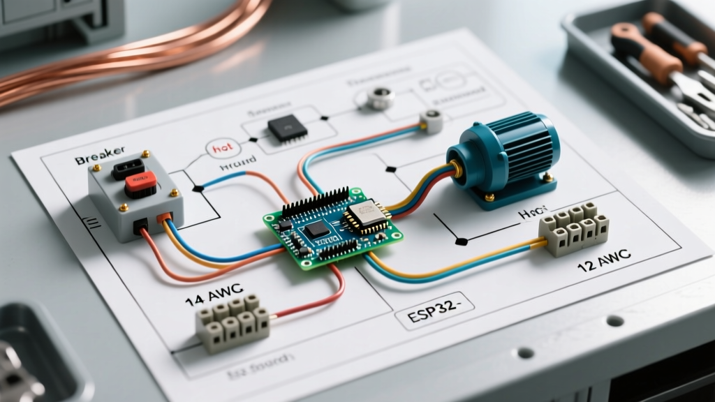

Decoding the Wiring Diagram for Water Well Pump Systems
Designing and executing a safe, code-compliant electrical feed for a submersible well pump requires more than simply connecting wires to a motor. As a core component of residential and agricultural infrastructure, the well pump circuit demands precise breaker sizing, appropriate wire gauge selection, and strict adherence to the National Electrical Code (NEC). Whether you are upgrading an aging system or installing a new Franklin Electric or Goulds Water Technology submersible pump, understanding the complete wiring diagram for water well pump configurations is critical to preventing motor burnout, voltage drop, and catastrophic panel failures.
According to the U.S. Environmental Protection Agency (EPA), private well owners are entirely responsible for the safety and reliability of their water systems. This includes ensuring that the electrical supply from the main breaker panel to the subterranean pump is protected against short circuits, ground faults, and environmental degradation. In this comprehensive panel and breaker guide, we will dissect the electrical pathway from the main service panel to the pressure switch and control box, providing actionable specifications for a 2026-compliant installation.
2-Wire vs. 3-Wire Submersible Configurations
Before pulling wire through conduit, you must identify your pump motor type, as this fundamentally alters the wiring diagram:
- 2-Wire Motors: The starting capacitor and relay are sealed inside the submersible motor housing. The wiring diagram requires only two hot wires (Line 1, Line 2) and a ground wire running directly from the pressure switch to the pump. This simplifies surface wiring but makes underground failures difficult to diagnose.
- 3-Wire Motors: The starting components are housed in a surface-mounted control box (e.g., Franklin Electric 3001000412). The wiring diagram necessitates three current-carrying conductors (Black, Red, Yellow) plus a ground. This is the preferred setup for pumps 1 HP and larger, as surface capacitors are easily replaceable without pulling the pump from the well casing.
Breaker Panel Sizing and Wire Gauge Matrix
Sizing your breaker and wire gauge incorrectly is the leading cause of nuisance tripping and motor overheating. Per NFPA 70 (NEC) Article 430, motor branch-circuit short-circuit and ground-fault protective devices must be capable of carrying the starting current (Locked Rotor Amps, or LRA) without tripping, while the wire must be sized for at least 125% of the Full Load Amps (FLA).
| Motor HP | Voltage | Full Load Amps (FLA) | Max Breaker Size (Inverse Time) | Min Copper Wire Gauge (THWN-2) |
|---|---|---|---|---|
| 1/2 HP | 230V | 6.0 A | 15A (2-Pole) | 12 AWG |
| 3/4 HP | 230V | 8.4 A | 20A (2-Pole) | 10 AWG |
| 1 HP | 230V | 10.0 A | 25A (2-Pole) | 10 AWG |
| 1.5 HP | 230V | 14.0 A | 30A (2-Pole) | 8 AWG |
| 2 HP | 230V | 18.0 A | 40A (2-Pole) | 6 AWG |
| 3 HP | 230V | 24.0 A | 50A (2-Pole) | 4 AWG |
Expert Panel Note: Always use a 2-pole breaker for 230V well pumps to ensure simultaneous disconnect of both ungrounded (hot) conductors. Never use two handle-tied single-pole breakers; modern NEC codes strictly require common-trip internal mechanisms for multi-wire branch circuits feeding motor loads.
Step-by-Step Panel to Pump Installation Guide
1. Main Panel Breaker Selection and Termination
Locate an available double-slot in your main service panel or sub-panel. For a standard 1 HP, 230V pump, install a 25A or 30A 2-pole breaker. If you are using a Square D Homeline panel, the HOM230 is the industry standard; for Siemens load centers, use the Q230. Strip the insulation back exactly 3/4 inch, insert the black and white wires (re-identified with black electrical tape or heat shrink to denote 230V) into the breaker terminals, and torque to the manufacturer's specification (typically 35-40 in-lbs). Connect the bare copper ground to the panel's equipment grounding bar.
2. The Disconnect Switch and GFCI Compliance
The wiring diagram for water well pump systems mandates a local disconnect switch within sight of the wellhead and control box. This is typically a 60A, 240V NEMA 3R outdoor-rated fused or non-fused disconnect.
The GFCI Nuance: Recent NEC code cycles have expanded Ground Fault Circuit Interrupter (GFCI) requirements for outdoor receptacles and certain equipment. However, hardwired submersible well pumps are generally exempt from GFCI protection unless specifically dictated by local amendments or if the circuit also feeds an outdoor receptacle. Applying a 30mA GFCI breaker to a deep-well submersible motor often results in nuisance tripping due to the natural capacitive leakage and high inrush currents of the motor winding. Stick to standard inverse-time thermal-magnetic breakers unless your local AHJ (Authority Having Jurisdiction) explicitly requires otherwise.
3. Control Box and Pressure Switch Termination
For a 3-wire system, the feed from the panel enters the pressure switch (e.g., Square D Pumptrol FSG2J21M4CP).
- Line Side: Connect the panel feed (Black and White/Re-identified) to the two outer brass terminals on the pressure switch.
- Load Side: Connect the wires leading to the control box to the two inner brass terminals.
- Grounding: The bare copper ground must pass through the pressure switch enclosure and bond to the green grounding screw, continuing uninterrupted to the control box and ultimately to the well casing ground clamp.
2026 Material Costs and Procurement Realities
Budgeting for a well pump electrical overhaul requires awareness of current copper and conduit pricing. As of early 2026, the cost of raw copper remains elevated. A 250-foot spool of 10/2 UF-B (Underground Feeder) direct burial cable will cost between $380 and $450. However, professional installers overwhelmingly prefer pulling individual THWN-2 conductors through 1-inch Schedule 40 PVC conduit. While the PVC conduit and fittings add roughly $120 to the material cost, it provides superior protection against rodent damage, soil shifting, and allows for future wire upgrades without trenching. A premium 3-wire control box for a 1 HP Franklin Electric motor currently retails for approximately $160 to $210, depending on the inclusion of advanced lightning arrestors.
Advanced Troubleshooting: Nuisance Tripping and Voltage Drop
If your newly wired pump circuit trips the breaker immediately upon startup, you are likely dealing with one of two issues:
Locked Rotor Amps (LRA) vs. Breaker Curve
Submersible motors draw 500% to 700% of their FLA for a fraction of a second during startup. A 1 HP motor with a 10A FLA might pull 60A momentarily. If your breaker is sized too close to the FLA (e.g., using a 15A breaker for a 10A motor), the magnetic trip mechanism inside the breaker will interpret the inrush as a short circuit. Always verify the maximum breaker size on the motor nameplate and the manufacturer's technical documentation.
Severe Voltage Drop
Voltage drop is the silent killer of well pumps. If the wire gauge is too small for the distance from the panel to the pump, the voltage at the motor terminals will sag below 207V (for a 230V system) during startup. This causes the motor to draw excessive amperage, overheat, and eventually fail.
The 5% Rule: The NEC recommends that the combined voltage drop for feeders and branch circuits not exceed 5%. For a 250-foot run to a 1.5 HP pump, 10 AWG wire will result in an unacceptable 7% drop. You must upsized to 6 AWG copper to maintain optimal motor torque and longevity. Always calculate voltage drop based on the total circuit length (panel to pump and back), which is double the trench depth.
By strictly following this wiring diagram for water well pump systems, sizing your breakers to handle motor inrush, and respecting voltage drop limitations, you ensure a reliable, code-compliant water supply for decades to come.