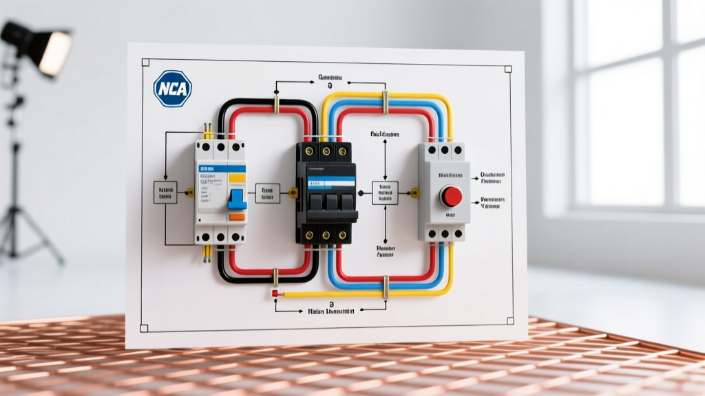

The Dual-Diagram Reality: Power vs. Control Circuits
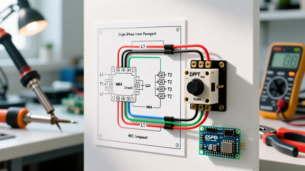
When reading electrical wiring diagrams for 3-phase AC motor starters, the most critical mistake novices make is confusing the physical wiring layout with the logical control sequence. In industrial motor control, you are actually dealing with two distinct but interconnected diagrams: the power circuit (which carries the high-current 3-phase load) and the control circuit (which governs the logic, timing, and coil actuation).
According to NFPA 70 (National Electrical Code), specifically Article 430 governing motors and motor circuits, these circuits must be distinctly identified and properly protected. A standard 480V 3-phase motor starter will step down the control voltage via a transformer (typically to 120V AC or 24V DC) to safely operate the contactor coils. If you attempt to trace a fault without isolating the control logic from the power delivery, you will waste hours chasing phantom voltage drops.
Safety Imperative: Before tracing any diagram with a multimeter, execute a strict Lockout/Tagout (LOTO) procedure. Verify zero energy on both the 3-phase line side (L1, L2, L3) and the control transformer secondary (X1, X2) using a CAT III or CAT IV rated meter.
Core NEMA Symbols You Must Recognize
North American motor control diagrams predominantly use NEMA (National Electrical Manufacturers Association) standard symbols. Unlike IEC symbols, which are common in European and modern PLC-driven systems, NEMA symbols are highly standardized for discrete hardwired components. Below is a quick-reference matrix for the most common elements you will encounter when reading electrical wiring diagrams for motor starters.
| Symbol / Designation | Component | Real-World Example & Terminal Mapping |
|---|---|---|
| M (Coil) | Motor Contactor Coil | Eaton C25 Series. Terminals: A1 (Hot), A2 (Neutral/Common). |
| OL (95-96) | Overload Relay NC Contact | Square D Class 9065. Terminals 95 (Line) and 96 (Load) break the control circuit during thermal trip. |
| F / R (Coils) | Forward / Reverse Contactors | NEMA Size 1 Reversing Starter. Mechanically and electrically interlocked. |
| Normally Open (NO) | Maintaining / Seal-in Contact | Auxiliary contact block (e.g., 13-14) wired in parallel with the momentary start pushbutton. |
| Normally Closed (NC) | Interlock / Stop Contact | Auxiliary contact (e.g., 21-22) wired in series with the opposing contactor coil to prevent simultaneous engagement. |
Step-by-Step: Tracing a Reversing Motor Starter Circuit
To truly master reading electrical wiring diagrams, let us trace a classic 3-phase reversing motor starter. This circuit is notorious for causing catastrophic phase-to-phase faults if wired or misinterpreted incorrectly. As of 2026, a robust NEMA Size 1 reversing starter (such as the Eaton Freedom series) retails between $380 and $450, largely due to the heavy-duty mechanical interlocks and silver-cadmium oxide contacts required for inductive switching.
1. The Power Circuit Trace
Start at the top of the diagram. Three phase lines (L1, L2, L3) enter the main disconnect and pass through the fuses or circuit breaker. They then feed the line side of the Forward (F) and Reverse (R) contactors.
Notice the phase rotation swap: To reverse a 3-phase AC motor, you must swap any two legs. On the diagram, you will see L1 and L3 cross over between the F and R contactors before tying together at the load side (T1, T2, T3) of the overload relay block, ultimately feeding the motor.
2. The Control Circuit Logic (Ladder Rung)
Move to the right side of the schematic (the ladder logic). The control power originates from the transformer secondary (X1 and X2).
The Sequence:
- Current leaves X1 and immediately passes through the Overload Relay NC contact (95-96). This is a critical safety design; if the motor draws excessive current and the bi-metallic strip trips, the 95-96 contact opens, instantly de-energizing whichever coil is active.
- The current reaches the Stop Pushbutton (NC).
- The circuit splits into two parallel branches: one for Forward, one for Reverse.
- Pressing the Forward Pushbutton (NO) sends current through the Reverse contactor's electrical interlock (NC) and finally to the Forward Coil (A1-A2).
- Once the F coil energizes, its parallel NO auxiliary contact (13-14) closes, bypassing the Forward pushbutton. This is the 'seal-in' or 'holding' circuit.
Common Failure Modes from Misreading Diagrams
When technicians rush through reading electrical wiring diagrams, they often rely on muscle memory rather than tracing the specific schematic in front of them. This leads to predictable, dangerous failure modes:
- Missing Electrical Interlocks: A diagram will show NC auxiliary contacts (e.g., F-21/22 and R-21/22) in series with the opposing coils. If a technician assumes the mechanical interlock block on the physical contactor is sufficient and omits the electrical interlock wiring, a welded contact on one contactor will result in both engaging simultaneously. This causes a massive phase-to-phase arc flash.
- Control Voltage Mismatch: Wiring a 24V DC PLC output directly to a 120V AC contactor coil because the technician looked at the power diagram's 480V rating and assumed the control circuit was also high voltage. This instantly destroys the PLC output card.
- Seal-in Circuit Feedback: Wiring the auxiliary holding contact on the load side of the contactor's main power terminals instead of the control transformer. When the motor stops, the collapsing magnetic field of the motor can induce enough back-EMF to keep the contactor weakly engaged, causing severe contact chattering and eventual welding.
Wire Sizing and Terminal Mapping Specifics
A professional wiring diagram doesn't just show logic; it implies physical constraints. For a standard 10 HP, 230V 3-phase motor (Full Load Amps ~28A), the Department of Energy's motor systems guidelines and NEC Table 310.16 dictate specific wire sizing.
- Power Circuit: 8 AWG THHN copper wire is required to handle the 125% continuous load multiplier (28A x 1.25 = 35A). Use crimped ferrule lugs on stranded wire before terminating at the contactor's box lugs to prevent strand splaying and subsequent hot spots.
- Control Circuit: 14 AWG THHN is standard for control wiring inside the panel, protected by a 5A or 10A Class CC fuse on the transformer secondary.
Real-World Troubleshooting Framework
When a motor fails to start, use your understanding of the diagram to isolate the fault logically. Grab a high-impedance multimeter, such as the Fluke 87V, and follow this voltage-tracing method:
- Verify Control Power: Measure across X1 and X2 on the control transformer. You should read exactly 120V AC (or 24V DC). If zero, check the primary control fuses.
- Check the Safety Chain: Place your black lead on X2 (Neutral/Common). Use your red lead to probe terminal 96 on the overload relay. If you read 120V, the overload has not tripped. If 0V, the OL is tripped or the 95 connection is loose.
- Test the Seal-in: Press the start button. If the contactor pulls in but drops out the moment you release the button, your auxiliary NO contact (13-14) is either miswired, physically broken, or the diagram you are reading doesn't match the physical auxiliary block installed on the contactor.
Final Thoughts on Diagram Literacy
Reading electrical wiring diagrams for motor control is not about memorizing every symbol; it is about understanding the flow of logic and the physical reality of the components. Always verify that the schematic revision date matches the physical panel. In older facilities, it is incredibly common to find panels where a previous technician added a limit switch or a timer relay without updating the master drawing. Trust the diagram as your map, but always verify the territory with your meter.