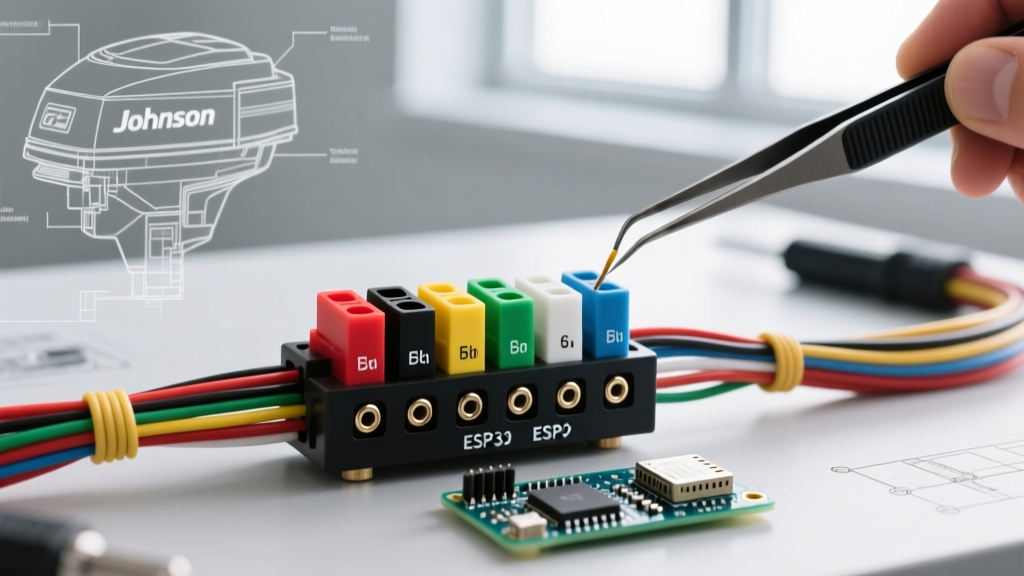

Understanding the Johnson & Evinrude 6-Pin Ignition Architecture
When diagnosing starting, charging, or kill-circuit failures on legacy OMC and BRP-manufactured engines, referencing an accurate wiring diagram for Johnson outboard ignition switch configurations is the mandatory first step. Johnson and Evinrude outboards (produced heavily through the 1970s until the brand's retirement in 2004) standardized around a universal 6-pin ignition switch layout. This architecture controls battery feed, ignition power, starter solenoid engagement, choke actuation, and the critical magneto kill circuit.
Unlike automotive ignition switches that simply cut power to stop the engine, marine outboards utilize a 'make-to-ground' kill system. Turning the key to the OFF position intentionally creates a short circuit between the magneto and the engine block, halting spark production. A failure in this specific circuit doesn't just prevent starting; it can result in a runaway engine that refuses to shut down via the key. This guide provides the exact terminal pinouts, multimeter testing procedures, and 2026 replacement part data required to troubleshoot and replace these switches safely.
⚠️ CRITICAL SAFETY WARNING: The Magneto Kill Circuit
Never attempt to start a Johnson outboard if the Black/Yellow kill wire is disconnected or the 'M' terminal is faulty. If the engine starts and the key cannot ground the magneto, you will be forced to stall the engine by choking the air intake or pulling the emergency lanyard, which poses severe physical and mechanical risks.
Standard 6-Pin Terminal Pinout & Wire Color Matrix
The universal Johnson/Evinrude 6-pin switch uses specific terminal letter designations and standard marine wire colors. While aftermarket harnesses may vary slightly, OEM BRP and OMC harnesses strictly adhere to the following color codes as outlined by the American Boat and Yacht Council (ABYC) Standards.
| Terminal ID | Label | Standard Wire Color | Function & State | Wire Gauge (AWG) |
|---|---|---|---|---|
| B | Battery | Red | 12V+ constant feed from battery/breaker. Hot at all times. | 10 AWG |
| I | Ignition | Purple | 12V+ to engine harness (regulator, gauges). Hot in ON and START. | 14 AWG |
| S | Start | Yellow/Red | 12V+ to starter solenoid. Hot ONLY in START position. | 12 AWG |
| C | Choke | Yellow/Red (or Purple/White) | 12V+ to choke solenoid when key is pushed IN. | 14 AWG |
| M | Magneto | Black/Yellow | Engine kill circuit. Grounded in OFF, Open in ON/START. | 16 AWG |
| G | Ground | Black | Switch ground for illumination and internal M-circuit routing. | 16 AWG |
Step-by-Step Multimeter Diagnostic Procedures
Before ordering replacement parts from the MarineEngine OEM Parts Catalog or aftermarket suppliers, you must verify whether the failure lies in the switch, the wiring harness, or the engine-side components. Use a high-quality digital multimeter (DMM) for these tests.
1. Testing the Kill Circuit (M to G Continuity)
- Disconnect the main battery negative terminal to prevent accidental shorts.
- Remove the ignition switch from the dashboard and unplug the 6-pin rear connector.
- Set your DMM to Continuity (Ohms/Ω).
- Place the red probe on the 'M' terminal and the black probe on the 'G' terminal.
- Key OFF: The meter should read near 0.0Ω (continuity). This confirms the switch is grounding the magneto.
- Key ON: The meter should read 'OL' (Open Loop). The ground is broken, allowing spark.
- Failure Mode: If you read 'OL' in the OFF position, the internal copper wiper is corroded or broken. The switch must be replaced immediately.
2. Voltage Drop Testing the Ignition Feed (B to I)
If your engine cranks but the gauges are dim, or the voltage regulator is underperforming, the ignition switch may be suffering from internal resistance.
- Reconnect the battery and harness. Set the DMM to DC Volts.
- Back-probe the 'B' (Red) wire and the 'I' (Purple) wire at the connector.
- Turn the key to the ON position (do not crank).
- Read the voltage drop. A healthy switch will show a drop of less than 0.1V. If the drop exceeds 0.5V, the internal contacts are heavily oxidized, robbing your engine's electrical system of critical voltage.
Common Failure Modes & Edge Cases
- The 'Runaway' Engine (M-Terminal Failure): As mentioned, if the Black/Yellow wire fails to ground internally, the key will not stop the engine. This is most common in saltwater environments where the rear switch boot has degraded, allowing moisture to corrode the M-terminal wiper.
- Neutral Safety Switch Interference: Many Johnson outboards route the 'S' (Start) terminal wire through a neutral safety switch on the shift lever before reaching the starter solenoid. If the key is turned to START and you hear a single 'click' from the dashboard but no crank, test for 12V at the solenoid. If absent, the issue is the neutral switch, not the ignition switch.
- Choke Solenoid Sticking: If the engine floods easily, the 'C' terminal may be shorting internally to the 'I' terminal, keeping the choke partially engaged while running. Verify that the 'C' terminal only shows 12V when the key is physically pushed inward.
'In marine electrical diagnostics, never assume a new out-of-the-box ignition switch is flawless. We frequently see aftermarket 6-pin switches with misaligned internal detents right out of the packaging. Always bench-test continuity on the M and G terminals before installing the switch into the helm.'
— Senior Marine Technician Field Notes
2026 Replacement Parts: OEM vs. Aftermarket Pricing
Because Johnson outboards are legacy products, genuine OEM BRP switches are becoming scarce and heavily marked up. In 2026, most professional marine mechanics rely on high-quality aftermarket equivalents that meet ABYC marine ignition standards.
| Part Number | Manufacturer | Approx. 2026 Price | Build Quality & Notes |
|---|---|---|---|
| 581948 | Genuine BRP / OMC | $85.00 - $110.00 | OEM fitment. Increasingly difficult to source; often backordered. |
| 18-5102 | Sierra Marine | $38.00 - $45.00 | Excellent aftermarket standard. Includes rubber dust boot and new nuts. |
| 150-581948 | CDI Electronics | $55.00 - $65.00 | Premium marine-grade contacts. Highly recommended for saltwater use. |
| MP39710 | Mallory Marine | $35.00 - $42.00 | Budget-friendly option. Good for freshwater/infrequently used vessels. |
Installation Best Practices & Corrosion Prevention
When installing your new Johnson ignition switch, the physical environment of the helm is just as critical as the electrical connections. Follow these steps to ensure a decade-long lifespan:
- Dielectric Grease is Mandatory: Apply a liberal amount of marine-grade dielectric grease (such as CRC or Permatex) to all 6 pins of the male connector before mating it to the new switch. This displaces moisture and prevents galvanic corrosion between the brass pins and copper wire crimps.
- Verify the Dust Boot: Ensure the rubber bezel and rear dust boot are seated tightly against the dashboard. If your helm is exposed to the elements, wrap the rear connector in self-amalgamating silicone rescue tape for an IP67-level waterproof seal.
- Torque Specifications: When tightening the mounting nut on the front of the dash, do not exceed 15 in-lbs. Over-tightening will crack the plastic switch housing or deform the internal bakelite wafer, causing the key cylinder to bind.
Frequently Asked Questions (FAQ)
Can I use a standard automotive ignition switch on my Johnson outboard?
No. Automotive switches use a 'break-to-stop' logic (cutting power to the coil), whereas Johnson outboards require a 'make-to-ground' logic (shorting the magneto to the block). Using an automotive switch will result in an engine that cannot be turned off with the key.
My key turns but the engine won't crank, and the gauges are dead. What's wrong?
This indicates a failure at the 'B' (Battery) terminal or the main inline fuse. Check for 12V at the Red wire on the back of the switch. If there is no voltage, trace the Red wire back to the starter solenoid or main battery breaker to find the open circuit.
Why does my engine crank but not start, unless I jiggle the key?
The 'I' (Ignition) terminal wiper is worn, causing an intermittent connection to the Purple wire. Without steady 12V on the Purple wire, the engine's voltage regulator/rectifier and fuel pump (if equipped) will not activate, preventing the engine from firing even though the starter is turning.