
Introduction to Forest River RV Electrical Architecture
Understanding the electrical wiring Forest River wiring diagram is essential for any RV owner, technician, or DIY enthusiast looking to maintain, upgrade, or troubleshoot their rig. Forest River, a subsidiary of Berkshire Hathaway and one of the largest RV manufacturers in North America, produces a vast array of models—from the lightweight Cherokee travel trailers to the luxury Georgetown Class A motorhomes. While the floorplans and amenities vary wildly, the underlying electrical architecture strictly adheres to the NFPA 1192 Standard for Recreational Vehicles and guidelines set by the Recreation Vehicle Industry Association (RVIA).
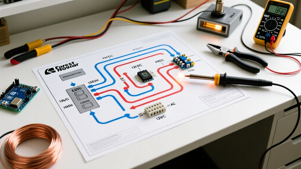
A standard Forest River schematic is essentially a dual-system map. It details the 120V AC (alternating current) shore power and generator circuits, alongside the 12V DC (direct current) house battery and chassis systems. Misinterpreting these diagrams can lead to catastrophic short circuits, blown converter units, or even electrical fires. This guide provides a deep-dive reference into reading these schematics, identifying critical nodes, and executing real-world troubleshooting.
Decoding RV Color Codes and Wire Gauges
Before tracing a single line on your Forest River schematic, you must understand the physical wires those lines represent. Unlike residential wiring governed strictly by the NEC, RV wiring follows specific RVIA color conventions. Below is the standard matrix you will encounter when cross-referencing your diagram with the physical loom behind your cabinetry.
| System Type | Wire Color | Function / Polarity | Typical Gauge (AWG) |
|---|---|---|---|
| 120V AC | Black | Hot / Line | 14 AWG (15A) / 12 AWG (20A) |
| 120V AC | White | Neutral | 14 AWG (15A) / 12 AWG (20A) |
| 120V AC | Green / Bare | Equipment Ground | 14 AWG (15A) / 12 AWG (20A) |
| 12V DC | Red / Black | Positive (+) | 10 AWG to 2/0 AWG (varies by load) |
| 12V DC | White | Negative / Ground (-) | 10 AWG to 2/0 AWG (varies by load) |
| Thermostat | Red | 12V DC Positive Feed | 18 AWG to 16 AWG |
Expert Warning: Never assume a previous owner or aftermarket installer followed RVIA color codes. Always verify voltage and polarity with a digital multimeter (such as the Fluke 117 or Klein MM400) before cutting into any wire loom, regardless of what the electrical wiring Forest River wiring diagram indicates.
Critical Components on the Schematic
When you pull the official schematic from the Forest River Owner's Portal, the diagram will look like a complex web of nodes. Here is how to identify and understand the three most critical components on the page.
1. The Power Distribution Center (PDC)
The PDC is the heart of the RV's electrical system. In most Forest River travel trailers and fifth wheels (like the Wildwood or Salem lines), this is a WFCO 8955 or a Power Dynamics PD4160 unit. On the wiring diagram, the PDC is depicted as a large central rectangle splitting into two distinct sections:
- 120V AC Breaker Panel: Shows standard thermal-magnetic breakers feeding the air conditioner (usually 30A), microwave (20A), and GFCI receptacles (15A/20A).
- 12V DC Fuse Block: Shows automotive-style ATO/ATC blade fuses. The diagram will map specific fuse slots to specific loads (e.g., Slot 4 for the water pump, Slot 8 for the awning motor).
2. The Converter/Charger Unit
The converter bridges the 120V AC and 12V DC systems. When plugged into shore power, it steps down 120V AC to 13.6V DC to run house loads and charge the battery bank. On the diagram, look for the converter wired directly to a dedicated 30A 120V breaker and heavy 6 AWG or 4 AWG cables leading directly to the 12V DC bus. Modern Forest River diagrams will also show the 4-stage smart charging logic (Bulk, Absorption, Float, and Equalization) integrated into the unit's internal logic board.
3. The Battery Disconnect and Latching Relay
High-end Forest River models utilize an Intellitec Battery Disconnect system. On the schematic, this is represented by a latching relay wired directly to the positive battery terminal via a massive 2/0 AWG cable, completely bypassing the main 12V PDC. This relay uses a momentary 12V pulse to flip a heavy-duty contactor, physically severing the house loads from the battery bank during storage to prevent parasitic drain from the LP gas detector and radio memory.
Advanced Integrations: Inverter/Charger Systems
If you are reading the electrical wiring Forest River wiring diagram for a 50-amp luxury fifth wheel (such as the Cedar Creek or Sabre lines) or a Class A motorhome, you will likely encounter an integrated Inverter/Charger, such as the Magnum Energy MS2812 or a Victron MultiPlus.
These diagrams are significantly more complex. They will show:
- AC Input/Output Routing: Shore power enters the inverter first, passes through an internal transfer switch, and then routes to the sub-panel.
- Massive DC Cabling: 2/0 AWG or 4/0 AWG pure copper welding cable connecting the inverter to the lithium or AGM battery bank.
- ANL Fusing: A 250A or 300A ANL fuse located within 18 inches of the battery positive terminal, a critical safety requirement explicitly detailed on the schematic.
- Remote ME-RC Panel: A low-voltage Cat5e-style data cable running from the inverter to the interior control panel for monitoring.
Step-by-Step Troubleshooting Using the Diagram
Let's apply the diagram to a real-world failure mode: The 12V water pump is not running, despite a fully charged battery bank reading 12.8V at the terminals.
- Locate the Load on the Schematic: Find the water pump icon on the diagram. Trace the positive (red) line back to the PDC. Note the fuse rating (typically 10A or 15A) and the specific slot number.
- Verify the Fuse and Bus Voltage: Pull the 15A blade fuse at the PDC. Use your multimeter to check for 12V+ at the load-side terminal of the fuse slot. If you read 0V, the issue is upstream (a blown main 12V feed fuse or a tripped 12V breaker near the battery).
- Check the Switch Loop: Most Forest River diagrams route the pump's positive wire through a momentary or toggle switch at the bathroom/kitchen sink before reaching the pump motor. Check for voltage drop across this switch. A reading of 12.8V on the input side and 10.5V on the output side indicates corroded internal contacts in the switch.
- Verify the Ground Path: This is where 80% of RV electrical faults hide. The diagram will show the pump's white negative wire routing to a localized ground bus bar, which then ties back to the main chassis ground. Inspect the localized bus bar for white corrosion (aluminum oxidation) or loose sheet-metal screws. Clean with a wire brush and apply dielectric grease.
Sourcing Official Forest River Schematics
Forest River does not publish a universal wiring diagram; schematics are highly specific to the exact model, floorplan, and production year. To obtain the correct electrical wiring Forest River wiring diagram for your rig:
- Forest River Owner's Portal: Register your VIN on the official Forest River website. Navigate to the "Manuals and Documents" section for your specific unit.
- Physical Binder: Check the owner's packet provided at the dealership PDI (Pre-Delivery Inspection). The 12V and 120V schematics are usually printed on 11x17 folded paper in the back of the main manual.
- Dealer Service Department: If you bought second-hand, contact the selling dealer's service department with your VIN. They can pull the exact build sheet and schematic from the Forest River dealer portal.
Final Safety Considerations
When modifying or repairing circuits based on your Forest River schematic, always disconnect both the 120V AC shore power cord and the negative terminal of the 12V DC battery bank. Upgrading to lithium iron phosphate (LiFePO4) batteries is a popular 2026 trend, but doing so requires reprogramming your WFCO converter's DIP switches or installing a dedicated DC-DC charger to prevent overcharging and thermal runaway. Always respect the ampacity limits defined in the diagram, and never replace a 15A fuse with a 20A fuse to bypass a recurring trip—find the short instead.