
Understanding the Western Unimount 3-Plug Relay Architecture
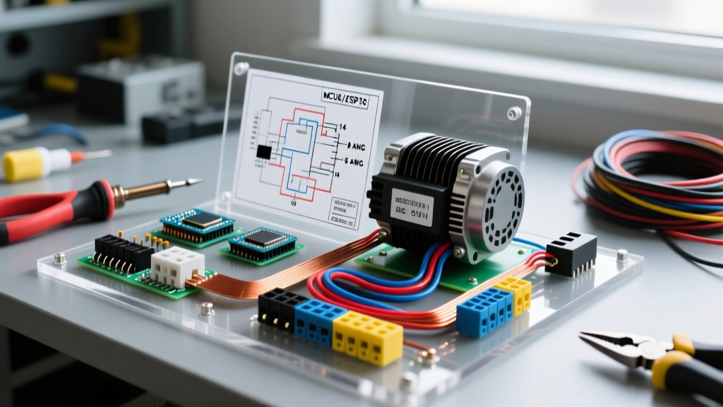
Integrating a Western Unimount snow plow into a Ford F-250 or F-350 Super Duty requires a precise understanding of both the plow's electrical demands and the truck's chassis-specific wiring pathways. The Western Unimount Pro and standard Unimount series predominantly utilize a 3-plug relay-based electrical system. Unlike modern multiplex (Fleet Flex) setups that communicate via CAN bus, the 3-plug system relies on heavy-duty mechanical relays and direct high-current copper pathways to command the hydraulic pump motor and lighting circuits.
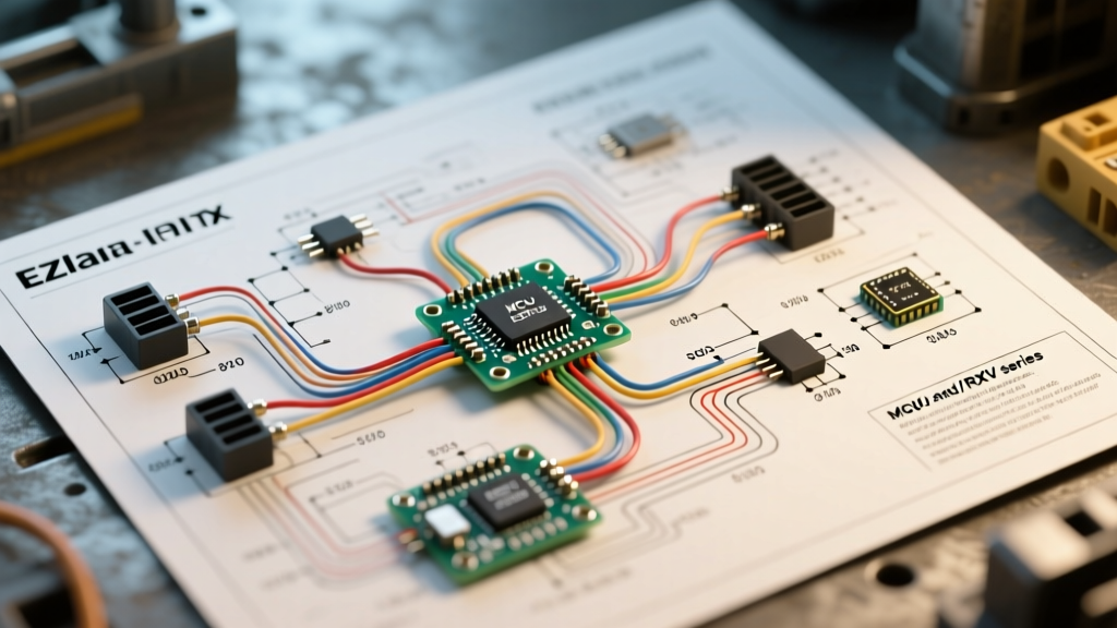
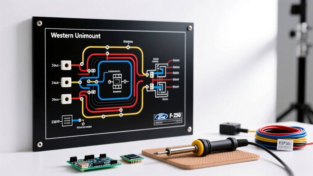
For Ford Super Duty applications, the truck-side harness (typically part number 64203 or 64203-1) must interface seamlessly with the plow-side harness (part number 64303). This guide provides the exact wiring diagram parameters, pinout matrices, and Ford-specific installation edge cases required for a reliable, code-compliant installation.
Ford Super Duty Pinout Integration Matrix
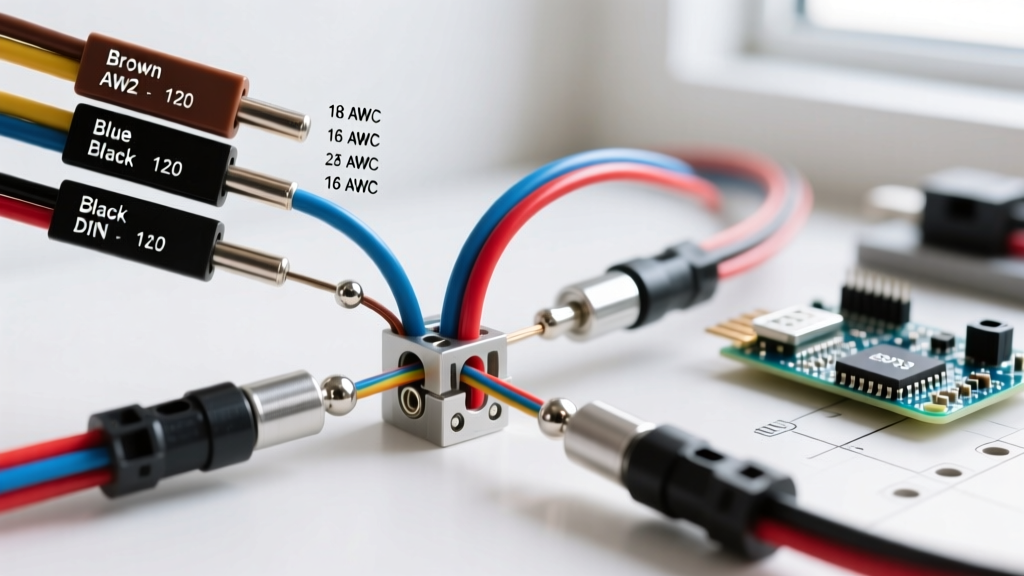
The 3-plug system divides responsibilities into three distinct connectors: Power/Ground, Left Lighting, and Right Lighting. Below is the vehicle-side integration matrix for routing the 64203 harness into the Ford F-250's factory lighting pigtails and power distribution center (PDC).
| Plug / Pin | Wire Color | Function | Ford F-250 Integration Point |
|---|---|---|---|
| Plug 1 (Power) | 2 AWG Red | Main Battery Positive | PDC Stud or Direct to Positive Terminal (w/ Mega Fuse) |
| Plug 1 (Power) | 2 AWG Black | Main Chassis Ground | Driver-side frame rail ground stud (M8 bolt) |
| Plug 2 (Left) | Brown | Tail/Marker Lights | Splice into factory left tail light harness (Brown wire) |
| Plug 2 (Left) | Yellow | Left Turn / Hazard | Splice into factory left turn signal (Yellow/Light Green) |
| Plug 3 (Right) | Green | Right Turn / Hazard | Splice into factory right turn signal (Orange/Light Blue) |
| Plug 3 (Right) | Black w/ White | Headlight Common Ground | Factory headlight ground ring terminal |
Wire Gauge and Solenoid Sizing Specifications
The hydraulic pump motor on a standard Western Unimount (often a Prestolite 1.5 kW unit) draws significant amperage under load. When pushing heavy, wet snow, the motor can spike to 180-220 amps. To prevent voltage drop and subsequent solenoid chatter, wire gauge selection must strictly adhere to SAE J1128 standards for low-tension primary cables.
| Circuit Segment | Minimum Wire Gauge (AWG) | Overcurrent Protection | Component Specification |
|---|---|---|---|
| Battery to Solenoid | 2 AWG Stranded Copper | 175A Mega Fuse | Terminals: 3/8" ring, heat-shrink sealed |
| Solenoid to Motor | 2 AWG Stranded Copper | N/A (Protected upstream) | White-Rodgers 586-902 Continuous Duty Solenoid |
| Control Circuit (Cab to Relay) | 14 AWG | 10A Inline ATC Fuse | Toggle switch or joystick harness |
| Lighting Harness (Main) | 12 AWG | 15A Auto-Reset Breaker | Weather-pack sealed connectors |
Step-by-Step Firewall Routing for the F-250
Routing the in-cab control harness through the firewall of a Ford Super Duty is a common pain point. Modern F-250s (2017 and newer) feature dense firewall insulation and limited pass-through grommets. Follow these steps to maintain the factory weather seal:
- Locate the Primary Grommet: Remove the driver-side lower kick panel trim. Look up behind the parking brake pedal assembly to locate the main 60-pin firewall pass-through grommet (Ford Part # HC3Z-14A468-A).
- Use a Fish Tape and Lubricant: Do not pierce the grommet blindly. Use a blunt-nose fish tape coated in dielectric silicone grease to gently slide past the existing factory wiring loom.
- Pull the Control Harness: Tape the 14-pin control connector tightly to the fish tape. Pull it into the cab, ensuring you leave at least 4 inches of slack on the engine bay side to prevent stress on the connector during engine movement.
- Seal the Grommet: Apply a bead of RTV silicone around the entry point to prevent water and carbon monoxide from entering the cab.
The 'Smart Alternator' Complication (2017+ Models)
Critical Warning for 2017+ Ford Super Duty Owners: Ford's Battery Management System (BMS) monitors current flow via a sensor located directly on the negative battery terminal. If you attach the plow's main 2 AWG ground wire directly to the negative battery post—bypassing the BMS sensor—the truck's PCM will not register the massive current draw of the plow motor. This results in the alternator failing to ramp up output, leading to severe undercharging and dead batteries mid-shift.
The Solution: Always attach the main plow ground to the designated chassis ground stud on the driver-side frame rail, or directly to the engine block ground strap. If you must modify the battery terminal connections, you are required to perform a BMS reset using an OBDII scan tool (such as the FORScan software with an OBDLink MX+ adapter) to recalibrate the alternator's charging profile.
Diagnostic Edge Cases and Failure Modes
When troubleshooting a Western Unimount on a Ford chassis, electrical gremlins often masquerade as hydraulic failures. Use a digital multimeter (DMM) to isolate these common edge cases:
- Solenoid Chatter During Lift: If the plow lifts in jerky increments, measure the voltage drop across the solenoid terminals while the motor is engaged. A drop greater than 0.5V indicates pitted internal contacts in the White-Rodgers solenoid. Replace the solenoid; do not attempt to sand the contacts.
- Headlights Flicker When Angling: This indicates a shared ground bottleneck. The Unimount lighting harness must have a dedicated, clean ground to the truck's frame. If it shares a ground with the Ford's factory headlight circuit, the high-amperage draw from the angle valves (S2/S3 coils) will backfeed into the lighting ground, causing flicker.
- Corrosion on Plug 1 Pins: The main power plug is highly susceptible to road salt intrusion. Apply a heavy coat of Nyogel 760G dielectric grease to the 2 AWG pins. Standard white lithium grease is insufficient and will wash out after three to four plowing events.
Sourcing, Costs, and Code Compliance
Building or repairing a Unimount harness requires high-quality, tinned marine-grade copper to resist the highly corrosive environment of salted roads. As of 2026, expect to pay between $280 and $340 for a complete OEM replacement truck-side harness (64203). A genuine White-Rodgers 586-902 solenoid typically retails for $75 to $95. Beware of $25 aftermarket solenoids found on generic marketplaces; they typically utilize intermittent-duty coils that will melt and fuse internally after 10 minutes of continuous heavy plowing.
For comprehensive schematic PDFs and relay testing flowcharts, technicians should consult the Western Plows Official Support Library. Furthermore, all high-current routing and overcurrent protection installations should comply with the safety thresholds outlined in NFPA 70 (National Electrical Code) Article 70 regarding mobile equipment grounding and overcurrent protection to prevent catastrophic chassis fires.
Frequently Asked Questions
Can I use a 2-plug harness on my newer Ford F-250?
No. The 2-plug system combines power and lighting into two large connectors, which was phased out in favor of the 3-plug system to separate high-amperage motor circuits from sensitive lighting circuits, reducing the risk of headlight burnout.
Why does my Ford F-250 dash display 'Check Charging System' when I plow?
This is directly related to the BMS sensor mentioned above. The PCM detects a voltage drop that it cannot reconcile with the alternator's commanded output. Ensure your grounds are on the chassis/engine block, not the battery post, and perform a BMS reset.