
Decoding the Wiring Diagram for Starter Solenoid Circuits
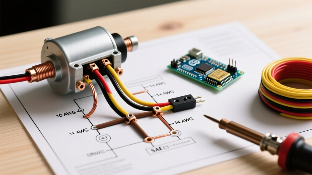
When examining a wiring diagram for starter solenoid configurations, most DIYers and junior technicians focus solely on terminal placement. However, the true reliability of a high-amperage cranking circuit relies heavily on precise wire gauge selection, strict adherence to SAE color codes, and proper termination techniques. A starter motor can draw anywhere from 150 to over 600 amps during initial cranking. If the wire gauge is undersized or the insulation rating is inadequate, the resulting voltage drop will starve the starter, while excessive resistance can melt harnesses and cause catastrophic thermal events.
In this comprehensive 2026 reference guide, we break down the exact American Wire Gauge (AWG) requirements, SAE J1560 color code standards, and mechanical torque specifications needed to build or repair a bulletproof starter solenoid circuit.
3-Terminal vs. 4-Terminal Solenoid Configurations
Before selecting your wire gauge, you must identify the solenoid topology. The wiring diagram for starter solenoid setups generally falls into two categories:
- 3-Terminal Solenoids (Common on GM, Honda, Toyota): Features a main Battery (B) stud, a Motor (M) stud, and an Ignition trigger (S) spade terminal. The S-terminal requires a low-amperage signal wire to pull the internal plunger.
- 4-Terminal Solenoids (Common on older Ford F-Series and agricultural tractors): Adds an Ignition bypass (I) terminal. Historically, this terminal supplied full battery voltage directly to the ignition coil during cranking, bypassing the ballast resistor used in older points-based ignition systems. In modern EFI swaps, the I-terminal is often left unused or repurposed for ECU cranking enrichment signals.
Wire Gauge (AWG) Selection Matrix for High-Amperage Cranking
Selecting the correct AWG is not just about the amp rating; it is a function of the total circuit length (battery positive to solenoid, plus solenoid to starter) and the acceptable voltage drop. According to NFPA 70 (NEC) guidelines adapted for automotive DC applications, maintaining a voltage drop below 0.5V across the entire cranking circuit is critical for optimal starter torque.
| Motor Cranking Amps (CCA) | Cable Length (One Way) | Recommended AWG Size | Est. Voltage Drop @ Peak Load |
|---|---|---|---|
| Up to 350 Amps | Under 5 feet | 4 AWG | 0.22V |
| 350 - 500 Amps | 5 to 10 feet | 2 AWG | 0.18V |
| 500 - 750 Amps | 10 to 15 feet | 1/0 AWG (One-Aught) | 0.14V |
| 750+ Amps (Diesel/Big Block) | Over 15 feet | 2/0 AWG (Two-Aught) | 0.10V |
| S-Terminal Trigger Wire | Any length | 12 AWG or 10 AWG | N/A (Low Amperage) |
Note: Always measure the actual routed path of the cable, not just the straight-line distance. Add 15% to your length calculation to account for bends, loom routing, and service loops.
SAE Color Code Standards for Solenoid Wiring
Adhering to SAE International standards (specifically J1560 and J1128) ensures that any technician troubleshooting the vehicle in the future can instantly identify circuit functions. While aftermarket kits often use generic red and black wires, professional harness builders utilize the following SAE color codes for starter circuits:
- Battery Positive (B-Terminal to Battery): Solid Red (SAE Code: RD). For heavy 1/0 or 2/0 AWG cables, red heat-shrink tubing at the termination points is the industry standard if the cable jacket is black.
- Motor Feed (M-Terminal to Starter): Solid Red or Red with Black Tracer. This is a switched high-amperage positive.
- Ignition Trigger (S-Terminal): Solid Yellow (YE) or Yellow with Red Stripe (YE/RD). This wire carries the 12V start signal from the ignition switch or ECU.
- Ignition Bypass (I-Terminal): Solid Brown (BR) or Red with White Stripe (RD/WT).
- Chassis/Engine Ground: Solid Black (BK). The starter motor must have a dedicated, clean ground path back to the battery negative, typically achieved via the engine block to chassis braided ground strap.
Wire Insulation Types: GXL vs. SXL vs. TXL
When sourcing wire for your starter solenoid wiring diagram, do not use standard PVC wire. Automotive engine bays require cross-linked polyethylene (XLPE) insulation. As of 2026, fine-strand SAE J1128 cables remain the benchmark:
- GXL (General Cross-Linked): Standard wall thickness. Excellent for general engine bay routing. Rated up to 125°C.
- SXL (Special Cross-Linked): Thicker insulation wall. Best for heavy 1/0 AWG battery cables that may be routed near exhaust headers or sharp chassis brackets. Rated up to 125°C.
- TXL (Thin Cross-Linked): Thin wall. Ideal for the 12 AWG S-terminal trigger wires where harness flexibility and tight bundle diameters are required. Rated up to 125°C.
Precision Termination and Torque Specifications
The most common point of failure in a starter circuit is not the wire itself, but the termination at the solenoid stud. A loose connection creates a high-resistance joint, leading to localized arcing and melted copper.
Crimping Heavy-Gauge Terminals
For 1/0 AWG and 2/0 AWG cables, standard pliers are entirely insufficient. You must use a ratcheting or hydraulic crimper to achieve a gas-tight mechanical bond. The Klein Tools 1005 (retailing around $115 in 2026) or the Astro Pneumatic 4704 hydraulic crimper are industry standards for compressing Delphi Packard 56-series or standard 3/8" ring terminals onto fine-strand battery cable. Always apply a layer of marine-grade heat shrink with internal adhesive lining to seal the crimp barrel against moisture and battery acid vapor.
Solenoid Stud Torque Specs
Most heavy-duty starter solenoids utilize copper or brass studs with a 3/8"-16 or 5/16"-18 thread. Because these studs are threaded directly into brittle bakelite or plastic solenoid housings, over-torquing will strip the threads, while under-torquing causes voltage drop.
- 5/16" Studs: Torque to 8 - 10 ft-lbs.
- 3/8" Studs: Torque to 12 - 15 ft-lbs.
- Terminal Stack Order: Solenoid Housing -> Star Washer -> Ring Terminal -> Flat Washer -> Hex Nut. Apply a thin coat of Noalox (anti-oxidant compound) to the copper surfaces before tightening to prevent galvanic corrosion.
Safety Warning: Always disconnect the negative battery terminal first, and reconnect it last. When working on the B-terminal of a starter solenoid, the cable is live directly from the battery. A dropped wrench across the B-terminal and the engine block will result in immediate, un-fused high-amperage arcing, which can cause severe burns or ignite fuel vapors.
Diagnosing Voltage Drop and Thermal Failure Modes
If your starter is cranking slowly despite a fully charged battery, do not immediately replace the starter. Consult your wiring diagram for starter solenoid pathways and perform a Voltage Drop Test. According to expert diagnostic procedures outlined by AutoShop101, voltage drop testing under load is the only accurate way to measure circuit health.
- Set your digital multimeter to DC Volts.
- Disable the ignition or fuel system so the engine will crank but not start.
- Place the red probe on the battery positive post and the black probe on the solenoid B-terminal stud (not the cable end). Crank the engine. A reading over 0.2V indicates excessive resistance in the positive battery cable.
- Move the red probe to the solenoid M-terminal stud and the black probe to the starter motor casing. Crank again. A reading over 0.2V indicates a poor connection at the motor cable or a failing internal solenoid contactor.
- Test the ground side: Red probe on the battery negative post, black probe on the starter motor casing. Readings above 0.1V indicate a corroded engine-to-chassis ground strap.
Thermal Failure Edge Case: If the S-terminal trigger wire is routed too close to exhaust manifolds without high-temp fiberglass sleeving, the insulation can melt, causing the 12V trigger signal to short to ground. This will blow the starter relay fuse in the under-hood PDC (Power Distribution Center) and result in a 'no-crank' condition.
Frequently Asked Questions
Can I use welding cable for my starter solenoid battery feed?
While welding cable is highly flexible and uses fine copper stranding similar to automotive battery cable, its EPDM or neoprene insulation is not rated for the continuous 125°C under-hood temperatures or the chemical exposure (oil, fuel, battery acid) defined by SAE J1128. For a reliable, long-term installation, always use SXL or GXL automotive primary wire.
Why does my Ford solenoid have four terminals, but I only use three?
The fourth terminal (I-terminal) is a legacy bypass for points-style ignitions. If you are running an HEI distributor, EFI, or modern coil-on-plug system, the I-terminal should be left empty and sealed with a silicone cap to prevent moisture ingress and short circuits.
What is the maximum acceptable length for a 12 AWG S-terminal trigger wire?
Because the S-terminal only draws about 10 to 15 amps momentarily to pull the solenoid plunger, a 12 AWG wire can easily span 15 to 20 feet from a dashboard-mounted start button or remote relay without suffering a voltage drop significant enough to affect solenoid engagement.