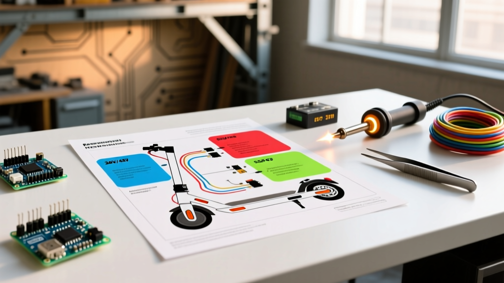

The Appliance Approach to E-Scooter Schematics
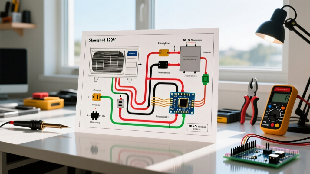
Treating an electric scooter as a complex DC appliance shifts your diagnostic mindset from guesswork to systematic schematic tracing. When you download an electric scooter wiring diagram PDF for a 36V or 48V brushless system, you are essentially looking at the blueprint of a high-current DC motor drive, a battery management system (BMS), and a low-voltage logic network. According to the U.S. Department of Energy's EV basics, understanding the flow of energy from the chemical storage medium to the kinetic output is the foundation of all electric mobility. By applying household appliance wiring methodologies—such as isolating the high-current 'load' circuits from the low-voltage 'control' circuits—you can safely diagnose, repair, or upgrade your scooter's electrical harness.
Decoding the Electric Scooter Wiring Diagram PDF
Most generic and branded e-scooter PDF schematics (from manufacturers like Razor, Segway, or generic Chinese OEM controllers) divide the wiring into three distinct logical layers. Recognizing these layers is critical before you pick up your wire strippers.
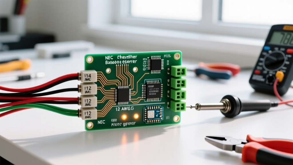
- High-Current Power Layer (12 AWG - 10 AWG): This includes the main battery positive (B+) and negative (B-), the motor phase wires, and the primary ground loops. These wires carry 15A to 30A continuous current.
- Logic and Sensor Layer (18 AWG - 22 AWG): This encompasses the Hall effect sensors, throttle potentiometers, brake interlock switches, and the DC-DC converter inputs. These operate strictly on 5V or 12V logic.
- Communication Layer (24 AWG - 26 AWG): Found in advanced setups, these are the UART or CAN bus lines connecting the dashboard display to the motor controller, often utilizing JST-SM 2.54mm or Molex connectors.
Standard Controller Pinout Color Codes
While your specific PDF may vary, 90% of brushless DC (BLDC) controllers follow a standardized color matrix. Deviating from this without verifying with a multimeter is the leading cause of fried MOSFETs.
- Red (Thick): Main Battery Positive (VCC)
- Black (Thick): Main Battery Negative (GND)
- Yellow, Green, Blue (Thick): Motor Phase Wires (U, V, W)
- Red (Thin): 5V Logic Power (for Hall sensors and Throttle)
- Black (Thin): Logic Ground
- Yellow, Green, Blue (Thin): Hall Sensor Signals (must match phase wire colors)
- White/Grey: Throttle Signal (0.8V to 4.2V sweep)
Step-by-Step: Wiring a 36V 250W Brushless Setup
When rebuilding a harness based on your PDF, follow this exact sequence to prevent logic board damage from voltage spikes. This procedure assumes a 10S (36V nominal, 42V peak) Li-ion battery pack and a standard 250W BLDC hub motor.
- Pre-Charge the Controller Capacitors: Never connect the main XT60 battery connector directly to the controller's thick red and black wires without a pre-charge circuit. The massive electrolytic capacitors inside the controller will draw an instantaneous inrush current exceeding 100A, which can weld the connector contacts and destroy the battery BMS. Use an anti-spark XT90-S connector or temporarily bridge a 100-ohm 5W resistor across the positive terminal for 3 seconds before making the final connection.
- Wire the BMS Balance Leads: If your PDF includes a 10S BMS, solder the balance leads in strict sequence. B0 (Black) goes to the main negative. B1 goes to the positive of the first cell group (4.2V), B2 to the second (8.4V), up to B10 (42.0V). Verify each pin with a multimeter before plugging it into the BMS board.
- Connect the Logic Harness First: Plug in the JST-SM connectors for the Hall sensors, throttle, and brake levers. Ensure the 5V red wire aligns perfectly with the 5V pin on both the controller and motor side. A reversed 5V/GND connection will instantly fry the motor's internal Hall sensors.
- Connect the Phase Wires: Bolt the thick Yellow, Green, and Blue wires from the controller to the corresponding motor wires. Use heat shrink tubing with adhesive lining to prevent moisture ingress and short circuits.
- Final Power Connection: Connect the main battery leads to the controller. Power on the ignition switch and verify the dashboard receives 36V-42V.
Expert Warning: According to diagnostic standards outlined in Fluke's official multimeter guide, always test the throttle signal wire for a smooth voltage sweep (0.8V at rest to 4.2V at full twist) before elevating the scooter's rear wheel for a live spin test. A stuck throttle signal will cause immediate runaway acceleration.
Wire Gauge Selection & Ampacity Matrix
Undersized wiring is the most common flaw in DIY e-scooter builds and cheap OEM replacements. The following matrix dictates the minimum acceptable wire gauge for a 36V/48V system drawing up to 25A continuous current. Always use high-strand-count silicone wire for flexibility and heat resistance.
| Wire Gauge (AWG) | Max Continuous Amps | Application in Scooter | Connector Type |
|---|---|---|---|
| 10 AWG | 30A - 40A | Main Battery to Controller (B+, B-) | XT60 or XT90 |
| 12 AWG | 20A - 30A | Controller to Motor Phase Wires | 4mm Bullet Connectors |
| 14 AWG | 15A - 20A | DC-DC Converter Input, Headlight Power | SM-2P or Spade Terminals |
| 18 AWG | 3A - 5A | Hall Sensors, Throttle, Brake Interlocks | JST-SM 2.54mm (3-pin/5-pin) |
| 22 AWG | 1A - 2A | UART/CAN Bus Display Communication | Molex PicoBlade |
Troubleshooting Matrix: Multimeter vs. PDF
When your scooter fails to engage, use your PDF to locate the test points, then apply the following diagnostic matrix. For deeper telemetry analysis on advanced builds, referencing Grin Technologies' Cycle Analyst documentation can help you interpret real-time shunt data and throttle mapping anomalies.
| Symptom | PDF Test Point | Multimeter Setting | Expected Reading & Action |
|---|---|---|---|
| Motor stutters or vibrates, won't spin | Hall Sensor Signal Wires (Thin Y/G/B) | DC Voltage (20V range) | Should toggle between 0V and 5V as wheel spins manually. If stuck at 0V or 5V, replace motor Hall sensors. |
| Dead throttle, no dashboard response | Throttle Signal Wire (White/Grey) | DC Voltage (20V range) | 0.8V at rest, 4.2V at full twist. If 0V, check 5V logic fuse or controller 5V regulator. |
| Scooter shuts off under heavy load | BMS P- and B- Terminals | DC Voltage (200V range) | Should read identical to battery main voltage. If P- drops to 0V under load, BMS is tripping on over-current or a balance cell group is below 2.8V. |
| Brake light stays on, motor cut-off engaged | Brake Interlock Switch Ground | Continuity / Ohms | Should be Open (OL) when released. If shorted, the brake lever microswitch is jammed or wires are pinched in the steering column. |
Common Failure Modes & Edge Cases
The 'Melted Phase Wire' Syndrome
A frequent edge case not always detailed in basic PDFs is the melting of the 12 AWG phase wires inside the motor axle. This occurs when the controller's phase current limit is set too high (e.g., 35A peak on a 250W motor rated for 15A continuous). The heat generated at the bullet connector interface degrades the solder joints inside the motor stator. Fix: Always use a programming cable to limit the controller's phase current to 1.5x the motor's continuous rating, and apply dielectric grease to all bullet connectors to prevent oxidation and resistance buildup.
5V Regulator Burnout in Hall Sensors
If your PDF shows the dashboard and the motor Hall sensors sharing the same 5V logic rail from the controller, a short in the dashboard wiring will pull the 5V rail to ground. This internal controller 5V LDO (Low Dropout) regulator will overheat and fail, taking the motor's ability to read rotor position with it. Fix: Isolate the dashboard power by wiring it to a dedicated 12V-to-5V DC-DC buck converter (like an LM2596 module, costing roughly $3) rather than relying on the controller's internal logic regulator. This $3 upgrade prevents a $45 controller replacement.