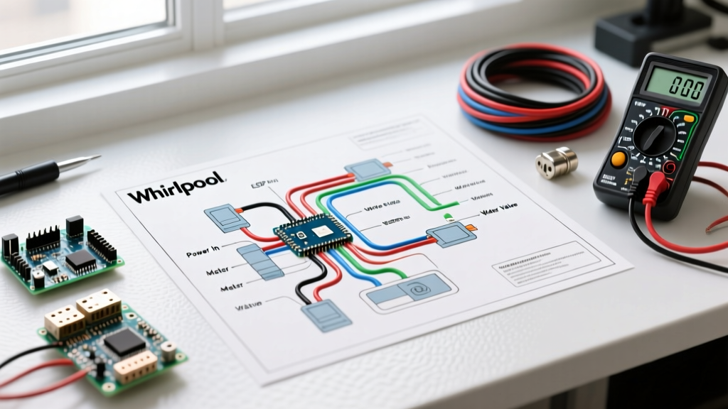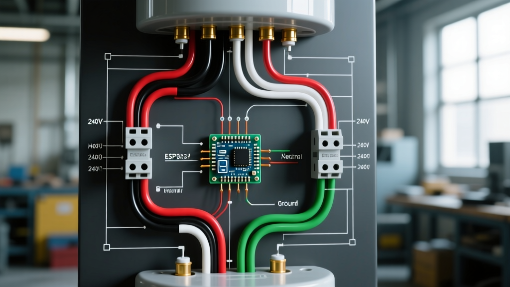

Understanding the Standard 240V Electric Water Heater Wiring Diagram
Wiring an electric storage water heater requires strict adherence to the National Electrical Code (NEC) and a clear understanding of non-simultaneous dual-element operation. Whether you are installing a high-efficiency Rheem Performance Platinum 50-gallon unit or replacing the heating elements in an older Bradford White RE2X50T6, the fundamental electric water heater wiring diagram remains consistent across most residential 240V applications. In 2026, with copper prices fluctuating and smart electrical panels like the SPAN panel becoming more common, ensuring your wire gauge and breaker sizing are perfectly matched to the appliance load is critical for preventing voltage drop, nuisance tripping, and fire hazards.
According to the U.S. Department of Energy, water heating accounts for roughly 18% of a home's energy use. A poorly wired circuit with undersized conductors will generate excess heat at the junction box, degrading the Romex insulation over time and wasting electricity through resistive losses. This guide provides a comprehensive diagram reference, NEC compliance matrix, and multimeter troubleshooting steps for 30A and 40A configurations.
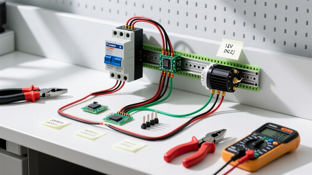
Core Circuit Components
- Double-Pole Breaker: Supplies 240V by connecting to both the A and B phases of your main service panel. Standard sizes are 30A (for 4500W/5500W elements) or 40A (for 6000W+ commercial elements).
- 10/2 NM-B Cable (Romex): Contains a black (hot), white (hot, must be re-identified), and bare copper (ground) wire. Rated for 30A under NEC Article 334.
- Upper Thermostat: Acts as the master controller. Houses the ECO (Energy Cut Off) high-limit switch that trips if water exceeds 150°F–170°F.
- Lower Thermostat: Operates as a slave switch, only receiving power when the upper tank has reached the set temperature.
Step-by-Step Schematic Reference: 4500W Dual Element Setup
Most residential electric water heaters utilize a non-simultaneous wiring scheme. This means the upper and lower elements never draw power at the exact same time, which keeps the maximum amperage draw under the 30A threshold even if both elements are rated at 4500W (which would theoretically draw 37.5A if run simultaneously).
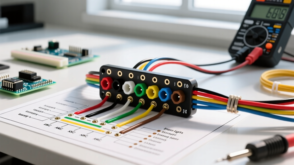
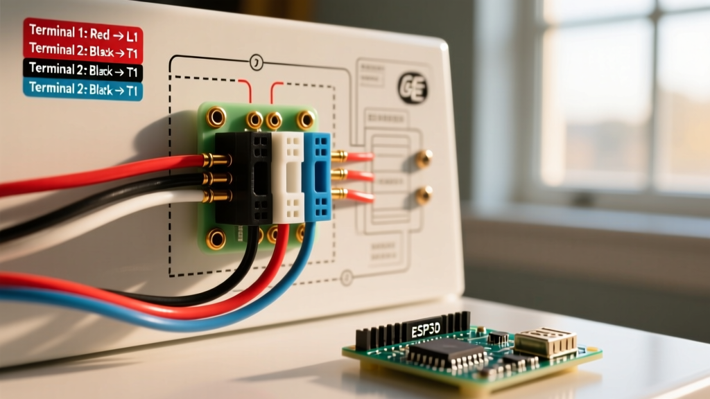
Wiring Flow Matrix (Text-Based Diagram)
1. Line 1 (Black Wire from Panel): Connects to the L1 terminal on the Upper Thermostat.
2. Line 2 (White Wire from Panel, taped Black/Red): Connects to the L3 terminal on the Upper Thermostat AND directly to the L4 terminal on the Lower Thermostat.
3. Upper Element Feed: A jumper wire runs from the Upper Thermostat's internal switch output to the top terminal of the Upper Heating Element. The bottom terminal of the Upper Element connects to the L2 terminal on the Upper Thermostat.
4. Lower Element Feed: A jumper wire runs from the Upper Thermostat's lower switch output (which only closes when the top tank is hot) to the L1 terminal on the Lower Thermostat. The Lower Thermostat then switches power to the Lower Heating Element.
5. Ground (Bare Copper): Connects directly to the green grounding screw inside the water heater's junction box, which is bonded to the steel tank chassis.
Wire Gauge, Breaker Sizing, and NEC Compliance Matrix
Sizing your breaker and wire correctly is dictated by NEC Article 422 (Appliances) and Article 210 (Branch Circuits). Because a water heater is considered a continuous load in some jurisdictions (running for 3 hours or more), the NEC 125% rule often applies, though standard residential storage tanks are frequently exempt from the continuous load multiplier if they are under 120 gallons. However, best practice and most local inspectors require the 125% safety margin.
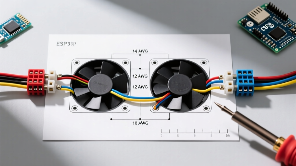
| Element Wattage | Voltage | Amperage Draw (Amps) | NEC 125% Rule Load | Required Breaker Size | Min. Copper Wire Gauge |
|---|---|---|---|---|---|
| 3800W | 240V | 15.8A | 19.75A | 20A or 25A (Dual Pole) | 12 AWG (12/2 NM-B) |
| 4500W (Standard) | 240V | 18.75A | 23.4A | 25A or 30A (Dual Pole) | 10 AWG (10/2 NM-B) |
| 5500W (High Recovery) | 240V | 22.9A | 28.6A | 30A (Dual Pole) | 10 AWG (10/2 NM-B) |
| 6000W (Commercial/Large) | 240V | 25.0A | 31.25A | 35A or 40A (Dual Pole) | 8 AWG (8/2 NM-B) |
NEC Code Alert: Under NEC 240.4(D), small conductor rules strictly limit 10 AWG copper to a maximum 30A overcurrent device. If you are installing a 6000W element setup requiring a 40A breaker, you must upgrade to 8 AWG wire, even if the manufacturer's literature suggests 10 AWG is sufficient for the raw amperage. Always defer to the NEC over manufacturer minimums.
120V vs. 240V Configurations: When to Step Down
While 240V is the undisputed standard for whole-home 40-to-80-gallon tanks, 120V electric water heater wiring diagrams are prevalent in specific edge cases. Understanding the difference is vital for RVs, off-grid solar setups, and point-of-use (POU) under-sink units.
120V Point-of-Use (POU) Wiring
Small 2.5-gallon to 6-gallon POU heaters (like the Bosch Tronic 3000T) often operate on 120V using a standard 15A or 20A single-pole breaker and 14/2 or 12/2 NM-B cable. In this diagram, the black wire goes to the thermostat, the white wire goes directly to the element, and the bare wire grounds the chassis. Recovery times on 120V are exceptionally slow; a 1500W element at 120V draws 12.5A and will take over 45 minutes to recover a 6-gallon tank.
Converting 240V to 120V (Not Recommended for Whole-Home)
Some DIYers attempt to wire a standard 4500W 240V tank to a 120V circuit by capping one hot wire. Do not do this. A 4500W element designed for 240V will only produce 1125W of heat when fed 120V (Power = Voltage² / Resistance). Your recovery time will quadruple, and the water will rarely reach a sanitary 120°F, risking Legionella bacteria growth.
Advanced Troubleshooting: Multimeter Diagnostics & Edge Cases
When a water heater fails to produce hot water, or immediately trips the 30A Square D HOM230CP breaker upon reset, you must isolate the fault using a digital multimeter. According to the Consumer Product Safety Commission (CPSC), electrical heating elements are a leading cause of appliance-related thermal events when internal shorts occur.
Step 1: Verify Incoming Voltage
Set your multimeter to AC Voltage (V~). Place one probe on the L1 terminal and the other on the L3 terminal at the upper thermostat. You should read between 235V and 245V. If you read 120V, you have lost one phase (a tripped half of the double-pole breaker or a loose neutral/phase bus bar connection in the main panel).
Step 2: Test Element Resistance (Ohms)
Turn off the breaker and disconnect the wires from the heating elements. Set the multimeter to Ohms (Ω). Touch the probes to the two screw terminals on the element.
- 4500W Element: Should read exactly 12.8 Ω.
- 5500W Element: Should read exactly 10.4 Ω.
- 3800W Element: Should read exactly 15.1 Ω.
If the multimeter reads 'OL' (Open Loop) or infinity, the internal coil is snapped and the element must be replaced. If it reads near 0 Ω, the element has shorted internally and is the cause of your breaker tripping.
Step 3: Test for Ground Faults (The Silent Killer)
Place one multimeter probe on the element's screw terminal and the other on the bare metal tank or the grounding screw. The reading must be 'OL' (infinity). If you get any resistance reading, the element's internal magnesium oxide insulation has failed, allowing current to leak into the water. This is a severe shock hazard and requires immediate element replacement.
Grounding and Bonding Requirements
Proper grounding is non-negotiable. The equipment grounding conductor (EGC) inside your 10/2 NM-B cable must terminate on the green grounding screw inside the water heater's junction box. Per NFPA 70 (NEC) Article 250.118, this wire provides the low-impedance path necessary to trip the breaker in the event of a ground fault.
PEX Plumbing Note: If your home uses PEX or CPVC plastic water lines instead of copper, the water pipes are not inherently grounded. While the NEC does not strictly require you to bond the water heater's metal chassis to the municipal water supply via a #6 bare copper wire if the EGC is present, many local inspectors and the Uniform Plumbing Code (UPC) mandate a supplemental bonding jumper across the hot and cold dielectric unions to ensure equipotential bonding. Always verify with your local AHJ (Authority Having Jurisdiction) before closing up the junction box.