
Bridging the Gap: Internal PC Wiring and External Panel Requirements
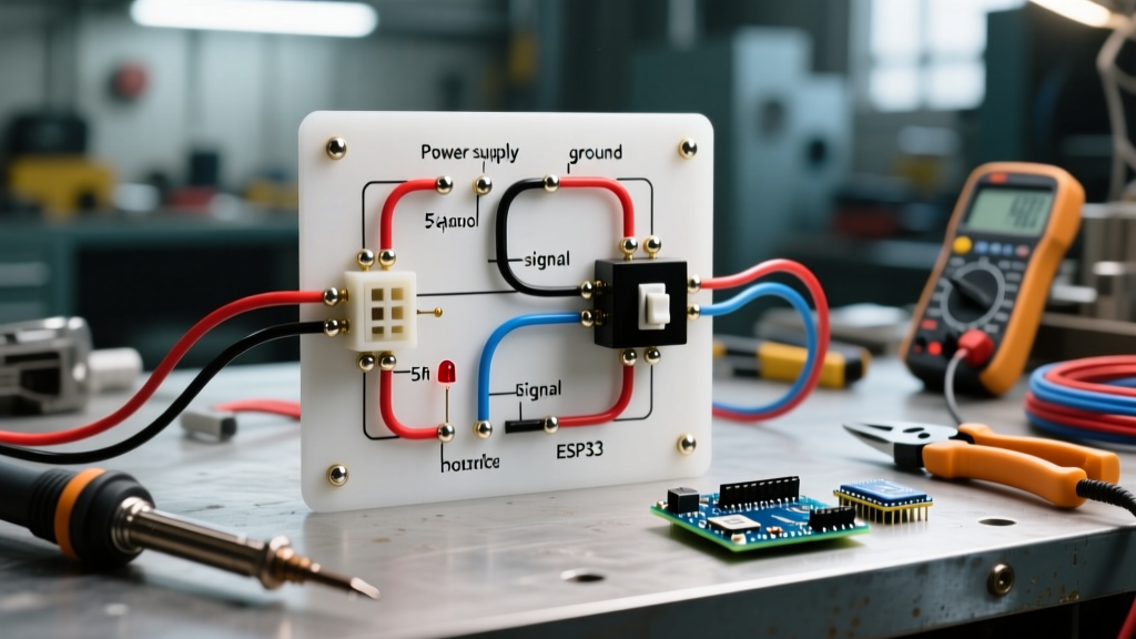
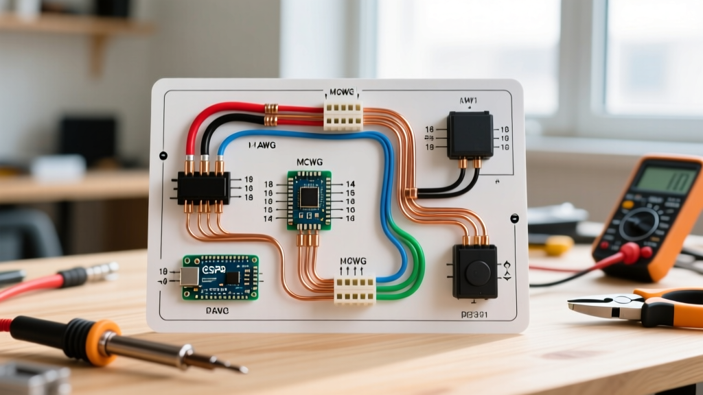
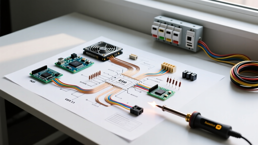
Most DIY enthusiasts and IT professionals look at a wiring diagram for computer power supply units (PSUs) strictly from an internal component-routing perspective. However, from a 'Panel & Breaker' electrical standpoint, a high-wattage PSU is a complex capacitive and inductive load that interfaces directly with your facility's main electrical panel. Whether you are wiring a dedicated workstation, a multi-GPU AI rendering rig, or a home server rack in 2026, understanding both the internal ATX pinouts and the external branch circuit requirements is critical to prevent nuisance tripping, voltage drop, and fire hazards.
This guide merges internal PC hardware schematics with National Electrical Code (NEC) panel guidelines, ensuring your high-draw system is powered safely from the breaker down to the motherboard.
The Panel Side: Sizing the Breaker and Wire for High-Draw PSUs
Before tracing the internal wiring diagram for your computer power supply, you must ensure the wall outlet is fed by an appropriately sized breaker and wire gauge. High-end ATX 3.1 power supplies, such as the Corsair HX1500i or Seasonic PRIME TX-1600, can pull massive continuous current.
NEC Continuous vs. Non-Continuous Load Rules
According to the National Fire Protection Association (NFPA 70), a continuous load is any load expected to run at maximum current for three hours or more. Rendering farms, cryptocurrency nodes, and heavy AI workloads easily exceed this threshold.
NEC Article 210.20(A) & 210.23: Branch circuit overcurrent devices must be rated at no less than 125% of the continuous load. Conversely, the load must not exceed 80% of the breaker's rated capacity for continuous operation.
The Math for a 1600W PSU:
- Max AC Draw: 1600W DC output / 90% efficiency (80+ Gold) = ~1777W AC input.
- Ampacity at 120V: 1777W / 114V (low-end voltage tolerance) = 15.5 Amps.
- Continuous Derating: 15.5A / 0.80 = 19.37 Amps.
Result: A standard 15A residential breaker will trip thermally within minutes. A 20A breaker is the absolute minimum, requiring 12 AWG copper conductors (e.g., 12/2 NM-B Romex, costing roughly $0.65 per foot in 2026). For commercial racks running on 208V/240V, the amperage drops significantly, allowing for denser deployments.
Decoding the Internal Wiring Diagram for Computer Power Supply
Once the panel and branch circuit are secured, we move to the internal wiring diagram. Modern ATX 3.0 and 3.1 power supplies utilize specific color-coded or pin-mapped standards to deliver power safely.
1. The 24-Pin ATX Motherboard Connector
The main 24-pin connector remains the backbone of the system. While modern PSUs use mostly black or custom-colored sleeves, the underlying wiring diagram adheres to strict voltage rails:
- Pins 1, 2, 12, 13 (+3.3V): Orange wires. Used for memory and some PCIe logic.
- Pins 4, 6, 19, 21 (+5V): Red wires. Powers USB peripherals, SATA drives, and RGB controllers.
- Pins 10, 11, 22, 23 (+12V): Yellow wires. The primary high-current rail for CPUs and GPUs.
- Pin 16 (PS_ON#): Green wire. Pulling this to ground (0V) signals the PSU to turn on.
- Pin 8 (PWR_OK): Gray wire. The PSU sends a +5V signal here to tell the motherboard that all rails are stable.
2. The 12V-2x6 (ATX 3.1) / 12VHPWR Connector
The most critical update in recent wiring diagrams is the 16-pin GPU connector. Replacing the older 8-pin PCIe layout, the Tom's Hardware Power Supply Connector Guide details how this single cable delivers up to 600W. The wiring diagram splits into two zones:
- 12 Power Pins: Six 12V lines and six ground lines, capable of handling 9.2A per pin.
- 4 Sense Pins (S1-S4): These low-voltage pins communicate the PSU's maximum power capability to the GPU. By grounding specific sense pins, the PSU tells the GPU whether it can safely draw 150W, 300W, 450W, or 600W.
Expert Warning: If the sense pins are not fully seated, the GPU may default to a safe 150W limit, causing severe throttling in high-end cards like the RTX 5090, or worse, arc across the 12V pins if partially inserted.
Data Matrix: PSU Wattage vs. Panel Breaker Requirements
Use the following reference table to match your power supply's maximum rated DC wattage to the correct electrical panel breaker and wire gauge, assuming a standard 120V North American residential circuit.
| Max PSU Wattage (DC) | Est. AC Draw (120V @ 90% Eff) | Min Breaker (Non-Continuous) | Min Breaker (Continuous 3hr+) | Required Copper Wire |
|---|---|---|---|---|
| 850W | 7.8A | 15A | 15A | 14 AWG |
| 1000W | 9.2A | 15A | 15A | 14 AWG |
| 1200W | 11.1A | 15A | 20A | 12 AWG (for 20A) |
| 1600W | 14.8A | 20A | 20A (Marginal) | 12 AWG |
| 2000W+ (Server) | 18.5A+ | 20A (Maxed) | Requires 240V Circuit | 12 AWG (240V) / 10 AWG |
Troubleshooting Nuisance Trips: Inrush Current and Breaker Curves
A common issue when wiring high-end computer power supplies to a dedicated panel circuit is 'nuisance tripping.' You flip the switch on the back of the PSU, and the 20A breaker instantly trips, even though the PC is off and drawing zero continuous load.
The Culprit: Capacitor Inrush Current
When a PSU is switched on, its internal bulk capacitors are completely discharged and act as a dead short for a few milliseconds. This causes an inrush current spike that can exceed 60 to 80 Amps. Standard residential thermal-magnetic breakers (like the Square D HOM120) are designed to trip on magnetic faults at 5x to 10x their rated current. An 80A spike on a 15A breaker (5.3x) sits right on the edge of the magnetic trip curve.
Solutions for Server Racks and Subpanels
If you are wiring a dedicated subpanel for a server rack or workshop testing bench, standard UL489 residential breakers are not ideal. According to Schneider Electric Inrush Current Guidelines, you should utilize DIN-rail mounted miniature circuit breakers (MCBs) with specific trip curves:
- Type B Breakers: Trip at 3-5x rated current. (Worst for PSUs, will trip constantly).
- Type C Breakers: Trip at 5-10x rated current. (Acceptable for standard gaming PCs).
- Type D Breakers: Trip at 10-20x rated current. (Ideal for multi-PSU server racks and heavy industrial equipment with massive inrush currents).
Additionally, high-end PSUs feature internal NTC (Negative Temperature Coefficient) thermistors that limit inrush current. If you are experiencing trips, ensure the PSU is of high quality; budget units often skimp on the NTC thermistor or the bypass relay that shorts it out after the capacitors are charged.
Step-by-Step: Upgrading to a Dedicated 20A PSU Circuit
If your existing 15A shared bedroom or office circuit is tripping under your workstation's load, follow these steps to install a dedicated line:
- Calculate the Load: Verify your PSU's max AC draw and apply the 125% NEC continuous load rule.
- Select the Breaker: Purchase a 20A single-pole breaker compatible with your panel (e.g., Square D HOM120CP for Homeline panels, approx. $12).
- Run the Wire: Pull 12/2 NM-B cable from the panel to a new single-gang work box. Keep the run under 50 feet to prevent voltage drop exceeding 3%.
- Install a 20A Receptacle: Use a NEMA 5-20R receptacle (identifiable by the T-shaped neutral slot) to physically prevent plugging standard 15A power strips into a high-draw dedicated line.
- Torque to Spec: Use an inch-pound torque screwdriver to tighten the breaker and receptacle lugs to the manufacturer's printed specifications (usually 12-15 in-lbs). Loose connections cause high-resistance arcing, a leading cause of electrical fires.
Summary
Reading a wiring diagram for a computer power supply is only half the battle for high-performance systems. By matching the internal ATX 3.1 pinouts and 12V-2x6 sense logic with external NEC-compliant branch circuits, proper wire gauges, and inrush-tolerant breakers, you ensure maximum uptime and safety for your most demanding electronic projects.