
Why High-Amp Electric Fans Demand a Relay
Upgrading to a high-performance electric cooling fan is one of the most effective ways to improve engine thermal management and reclaim parasitic horsepower. However, modern high-flow fans, such as the SPAL VA09-AP50/C61A or Maradyne M162K, draw massive amounts of current. While their running amperage might sit around 15A to 20A, their Locked Rotor Amperage (LRA) or inrush current upon startup can easily spike past 35A for several milliseconds. Routing this kind of electrical load through a standard dashboard toggle switch or a factory engine control unit (ECU) output will result in melted switches, fried traces, or catastrophic harness fires.
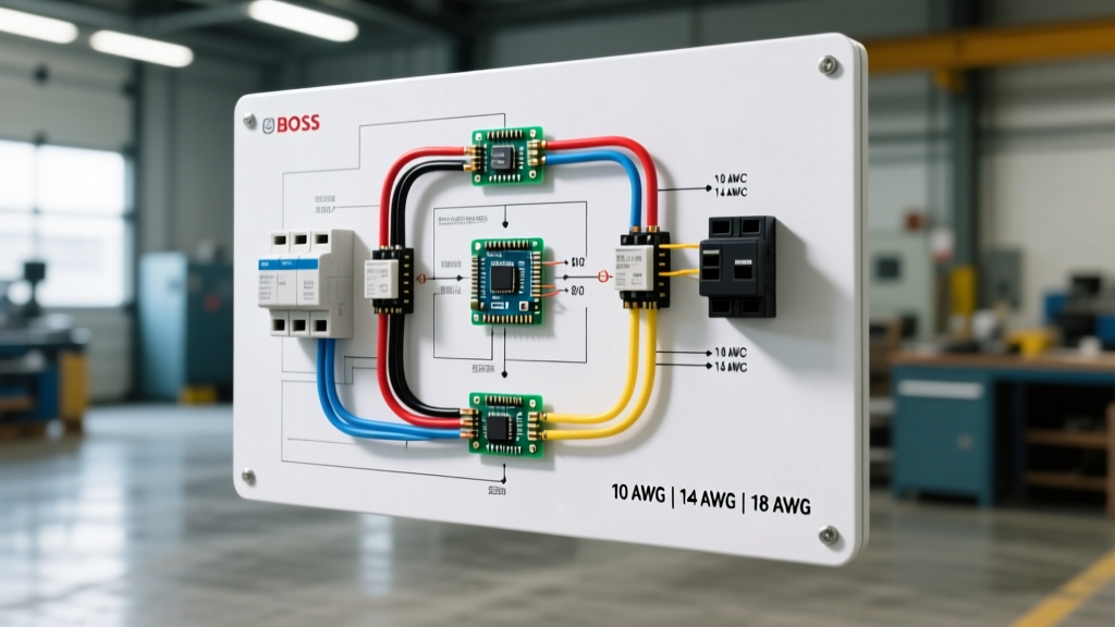
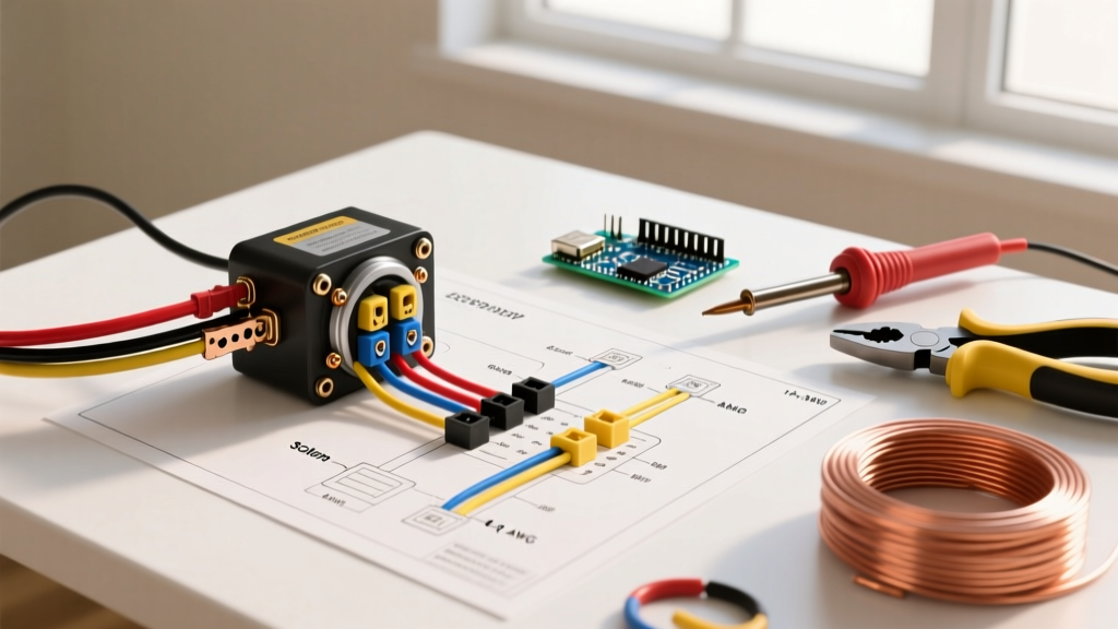
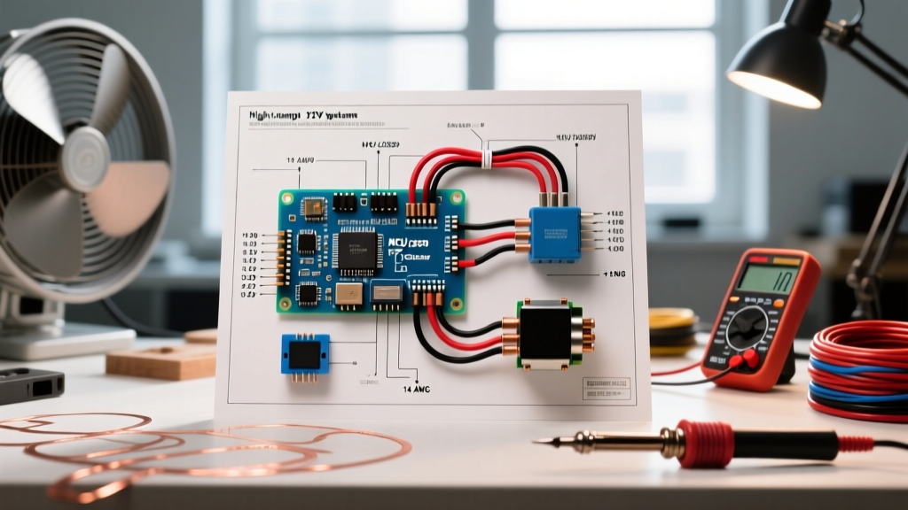
This is where a proper electric fan wiring diagram with relay becomes non-negotiable. A relay acts as a heavy-duty electromagnetic switch, allowing a low-amperage control circuit to safely trigger a high-amperage power circuit. In this comprehensive reference guide, we break down the exact schematic, component sizing, and advanced protection techniques required for a bulletproof 12V automotive or off-road fan installation in 2026.
Anatomy of the Standard 4-Pin Automotive Relay
The vast majority of high-amp fan setups utilize a standard 4-pin ISO mini or micro relay, governed by the DIN 72552 terminal numbering standard. Understanding these four pins is the foundation of reading any fan wiring diagram.
- Terminal 30 (Power In): This is your heavy-gauge power feed directly from the battery positive post. It is 'hot' at all times and must be protected by a fuse located within 18 inches of the battery.
- Terminal 87 (Power Out): This is the switched heavy-gauge output that delivers power to the electric fan's positive terminal when the relay is energized.
- Terminal 85 (Coil Ground): This pin grounds the internal electromagnetic coil. It can be tied to a clean chassis ground or, in advanced setups, controlled by the ECU's ground-switching driver.
- Terminal 86 (Coil Power): This pin receives the 12V trigger signal to energize the coil. This is typically sourced from an ignition-switched fuse, a thermostat switch, or a PWM (Pulse Width Modulation) controller output.
Expert Note: Never use a 5-pin relay (which includes an 87a normally-closed terminal) for a simple cooling fan unless you are wiring a dual-speed setup or a specific fail-safe circuit. The unused 87a terminal can cause arcing or short circuits if left exposed to moisture and road debris.
Component Bill of Materials (BOM) & Wire Sizing
The most common failure point in aftermarket fan wiring is not the relay itself, but the undersized wiring and improper fusing feeding it. According to data from the Engineering Toolbox wire gauge standards, voltage drop over distance severely impacts fan motor lifespan. A fan receiving 11.5V instead of 13.8V will draw more amperage to compensate for the lost wattage, generating excess heat.
| Component | Specification / Rating | Estimated Cost (2026) | Notes & Best Practices |
|---|---|---|---|
| Main Relay | Bosch 0332014150 (30A) or Littelfuse 40A | $9.00 - $14.00 | Always use sealed, waterproof relays with integrated bracket mounts. |
| Power Wire (30 to 87) | 10 AWG TXL (Cross-linked) | $0.85 / ft | TXL insulation withstands 125°C. Avoid PVC/THHN near exhaust headers. |
| Control Wire (85/86) | 16 AWG GXL | $0.45 / ft | Sufficient for the <1A coil draw; keeps harness bulk minimal. |
| Main Fuse | 40A Maxi-Fuse or MIDI-Fuse | $6.50 | Must handle inrush spikes without nuisance blowing. Avoid ATC mini-fuses. |
| Flyback Diode | 1N4004 Rectifier Diode | $0.10 | Mandatory if the relay coil is triggered by an ECU or sensitive PWM. |
| Connectors | Adhesive-Lined Heat Shrink Ring Terminals | $0.40 ea | Nylon or vinyl crimps will vibrate loose and cause high-resistance arcing. |
For deeper insights into automotive relay load capacities and contact materials, refer to the Littelfuse Automotive Relay Application Guide, which details how tungsten and silver-tin oxide contacts handle high inductive motor loads.
The Flyback Diode: Protecting Your ECU and PWM Controllers
One of the most critical, yet frequently omitted, elements in a modern electric fan wiring diagram with relay is the flyback diode. When the 12V trigger signal to the relay coil (Terminal 86) is removed, the collapsing magnetic field inside the coil generates a massive reverse-voltage spike—often exceeding 100V for a fraction of a millisecond. This phenomenon, known as inductive kickback, will instantly destroy the internal driver transistors of an engine ECU or a delicate aftermarket PWM fan controller.
How to Wire the Flyback Diode
- Obtain a standard 1N4004 rectifier diode.
- Identify the cathode (the end with the silver stripe) and the anode.
- Connect the cathode (stripe) to Terminal 86 (the positive trigger side of the coil).
- Connect the anode to Terminal 85 (the ground side of the coil).
When the circuit is active, the diode blocks current. When the circuit is switched off, the reverse voltage spike is safely recirculated through the diode and dissipated as a tiny amount of heat, protecting your expensive control modules. If you are wiring a standalone harness using a simple mechanical thermostat switch (like the Hayden 3653), the diode is optional but still recommended to prevent arcing across the thermostat's internal contacts, extending its mechanical life.
Step-by-Step Execution & Routing Standards
Adhering to the NFPA 70 (National Electrical Code) principles for mobile and vehicular DC applications ensures long-term reliability. Here is the professional execution sequence:
- Step 1: Battery to Fuse. Cut a length of 10 AWG TXL wire. Crimp a heavy-duty ring terminal on one end and connect it directly to the positive battery post. Measure exactly 12 to 18 inches down the wire, cut it, and install an inline Maxi-Fuse holder with a 40A fuse. This protects the entire harness in the event of a dead short.
- Step 2: Fuse to Relay (Pin 30). Run the remaining 10 AWG wire from the fuse holder to Terminal 30 on the relay. Secure it with a closed-end ring terminal or a high-quality spade connector.
- Step 3: Relay to Fan (Pin 87). Route 10 AWG wire from Terminal 87 to the positive terminal on the electric fan motor. Ensure this wire is loomed in split-nylon tubing and zip-tied away from moving belts, exhaust manifolds, and steering shafts.
- Step 4: Fan Ground. Ground the fan motor directly to the engine block or cylinder head using a dedicated 10 AWG ground strap. Do not rely on the radiator support or chassis sheet metal for the return path, as paint and powder coating will introduce severe voltage drop.
- Step 5: Control Circuit. Run 16 AWG wire from an ignition-switched 12V source to Terminal 86. Wire Terminal 85 to your trigger switch, thermostat, or ECU ground output. Install the 1N4004 diode across 85 and 86 as detailed above.
Troubleshooting Matrix: Diagnosing Common Fan Failures
Even with a perfect schematic, environmental factors and component fatigue can cause issues. Use this diagnostic matrix to isolate faults quickly.
| Symptom | Probable Cause | Diagnostic Action & Fix |
|---|---|---|
| Relay clicks loudly, but fan does not spin. | Pitted internal contacts (30 to 87) or open motor winding. | Use a multimeter to check for 12V at the fan connector while the relay is clicked. If 12V is present at the connector but the fan is dead, the motor brushes are worn. If 0V is at the connector, replace the relay. |
| Fan runs, but relay gets extremely hot to the touch. | Undersized relay or excessive voltage drop across contacts. | Verify the relay is rated for at least 30A continuous. Measure voltage drop across pins 30 and 87 while running; a drop greater than 0.2V indicates failing internal contacts. |
| Fuse blows instantly upon fan startup. | Dead short in the 87-to-fan wiring, or seized fan motor. | Disconnect the fan motor. Replace the fuse and trigger the relay. If the fuse holds, the fan motor is seized or internally shorted. If it blows again, inspect the 10 AWG power wire for pinched insulation against the chassis. |
| ECU throws a code or PWM controller resets when fan engages. | Missing flyback diode causing inductive voltage spike. | Install a 1N4004 diode across pins 85 and 86, ensuring correct polarity (stripe to 86). |
| Fan runs at half speed or lacks cooling power. | Severe voltage drop due to poor ground or undersized wire. | Measure voltage directly at the fan motor terminals while running. If it reads below 12.5V, clean the engine block ground strap or upgrade the wiring to 8 AWG. |
Final Thoughts on Harness Protection
A correctly executed electric fan wiring diagram with relay does more than just make the fan spin; it ensures the electrical system remains safe under the extreme thermal and vibrational stresses of an engine bay. Always use adhesive-lined heat shrink terminals rather than bare metal crimps, as the adhesive seals out moisture and prevents the green corrosion that inevitably increases resistance over time. By sizing your TXL wiring correctly, utilizing high-amperage Maxi-fuses, and implementing flyback diode protection for sensitive electronics, your high-amp cooling system will deliver reliable, static-free performance for the life of the vehicle.