
Understanding the Jetson E-Bike Electrical Architecture
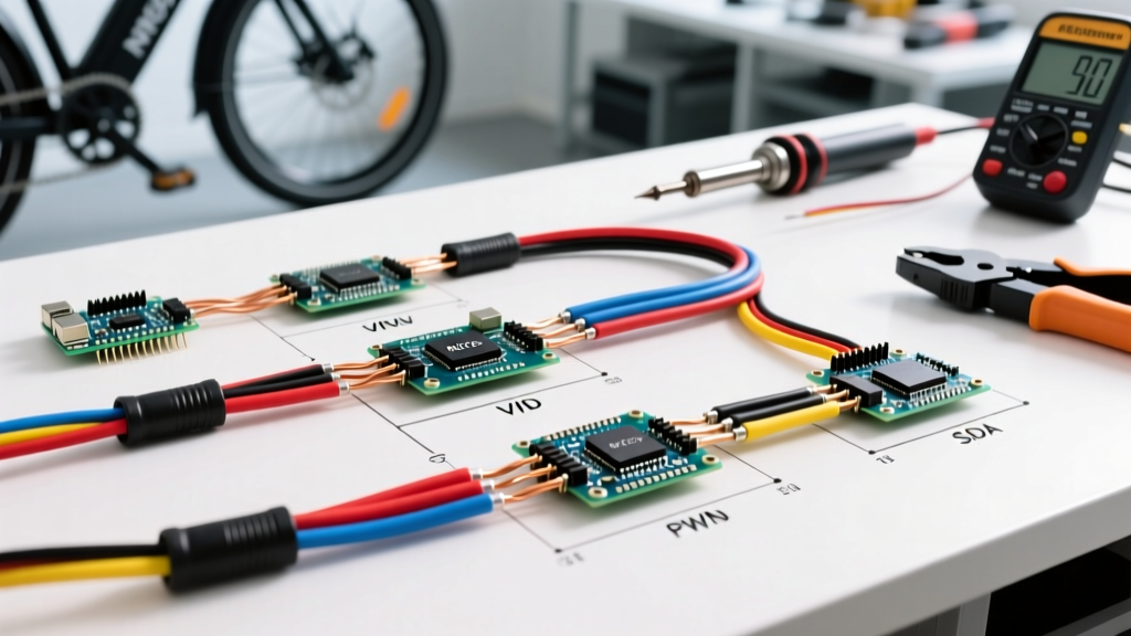
Jetson e-bikes, including popular commuter and folding models like the Jetson Metro, Jetson Bolt Pro, and Jetson Element, rely on a centralized motor controller to manage power distribution. Whether you are repairing a severed harness, upgrading to a higher-capacity battery, or replacing a burnt-out controller, understanding the underlying Jetson electric bike wiring diagram is critical. Modern Jetson models utilize a 36V or 48V DC architecture, governed by a brushless DC (BLDC) motor controller that processes inputs from the throttle, Pedal Assist System (PAS), and brake cut-offs.
Unlike generic DIY e-bike builds, Jetson controllers often use proprietary or semi-proprietary pinouts for their displays and peripherals, while relying on industry-standard connectors for high-current paths. Before cutting, splicing, or soldering any wires, it is imperative to map the harness correctly to avoid catastrophic short circuits or irreversible damage to the hall sensors.
Essential Tools and Wire Gauge Matrix
Using the incorrect wire gauge is a leading cause of voltage sag and melted connectors in e-bike systems. Below is the definitive wire gauge and connector matrix for Jetson 36V and 48V systems. Always use high-strand-count silicone-insulated wire for flexibility and heat resistance.
| Circuit Path | Recommended Wire Gauge | Standard Connector Type | Max Continuous Current |
|---|---|---|---|
| Battery to Controller (Main) | 12 AWG - 14 AWG | XT60 (36V) / XT90 (48V) | 30A - 45A |
| Controller to Motor (Phases) | 14 AWG | 4mm Gold Bullet Connectors | 25A - 35A |
| Motor Hall Sensors | 22 AWG - 24 AWG | JST-SM 6-Pin (2.54mm pitch) | < 0.5A |
| Throttle / PAS / E-Brakes | 20 AWG - 22 AWG | JST-SM 3-Pin / 2-Pin | < 0.2A |
Step 1: High-Current Battery and Controller Wiring
The main power loop connects the battery pack's Battery Management System (BMS) to the controller's main capacitors. In the Jetson Bolt Pro (36V 10Ah), this is typically handled by an XT60 connector.
The Anti-Spark Precaution
When connecting a fully charged Jetson battery to the controller, the inrush current charging the controller's capacitors can cause a massive spark. Over time, this spark pits the XT60 contacts, increasing resistance and generating excess heat. To prevent this:
- Use an Anti-Spark Connector: Upgrade your standard XT60 to an XT60-S (anti-spark), which features a built-in resistor to slowly pre-charge the capacitors.
- Install a Loop Key: For 48V models like the Jetson Metro, routing the main positive wire through a heavy-duty loop key with a pre-charge resistor is highly recommended.
Expert Warning: Never bypass the main fuse or BMS discharge limits. If your Jetson controller is rated for a 22A continuous draw, ensure your battery BMS is rated for at least 25A to 30A continuous to prevent unexpected cut-offs under heavy load, such as climbing steep inclines.
Step 2: Motor Phase and Hall Sensor Integration
The BLDC hub motor requires two distinct harnesses: the thick phase wires and the thin hall sensor wires. Miswiring these will result in a stuttering motor, excessive heat, or immediate controller failure.
Phase Wires (Yellow, Green, Blue)
Connect the three 14 AWG phase wires from the controller to the corresponding motor wires. While the color coding (Yellow-to-Yellow, Green-to-Green, Blue-to-Blue) is standard across most Jetson models, some aftermarket replacement controllers may require phase swapping if the motor spins backward or runs roughly. If the motor stutters and draws high current without spinning, swap any two phase wires (e.g., Yellow and Blue) to reverse the commutation sequence.
Hall Sensors (5-Pin Logic)
The hall sensors tell the controller the exact rotor position for smooth startup. The standard 5-pin JST-SM layout is:
- Red: +5V DC (Power)
- Black: Ground (GND)
- Yellow, Green, Blue: Signal A, Signal B, Signal C
Failure Mode: If the 5V red wire shorts to a signal wire, it will instantly fry the hall sensors inside the motor hub. Always use a multimeter to verify 5V on the red wire before plugging in the JST connector.
Step 3: Peripheral Wiring (Throttle, PAS, and Display)
Jetson controllers use low-voltage signal wires for rider inputs. The most common peripheral harness is the 1-to-4 split cable, which terminates in waterproof JST-SM connectors.
Throttle and PAS Pinouts
The thumb throttle and Pedal Assist System (PAS) both operate on a 0.8V to 4.2V signal range. The standard 3-pin configuration is:
- Red: +5V
- Black: Ground
- White or Green: Signal Output
PAS Alignment Tip: When wiring the PAS sensor on a Jetson Element or Metro, ensure the magnet ring on the crank arm maintains a precise 2mm to 3mm gap from the sensor. If the gap is too wide, the controller will not register pedaling, resulting in a 'Pedal Assist Not Engaging' fault.
Step 4: Safety Cut-Offs and Brake Sensors
E-brake cut-offs are critical safety features that sever power to the motor the moment you pull the brake lever. Jetson typically uses Normally Open (NO) mechanical brake sensors. In this configuration, pulling the brake lever closes the circuit, pulling the signal wire to ground and triggering the controller's interrupt routine.
If you are upgrading to hydraulic brakes with digital cut-off switches, ensure the switches are also Normally Open. Wiring a Normally Closed (NC) switch into a Jetson controller designed for NO switches will result in a permanent motor lockout, as the controller will read the brake as constantly engaged.
Troubleshooting Common Jetson Controller Faults
When a wiring error occurs, the Jetson LCD display will output specific error codes. Use this diagnostic matrix to trace the wiring fault:
| Error Code | Component | Wiring Fault / Action Required |
|---|---|---|
| E07 | Motor / Hall Sensors | Check 5-pin hall connector. Look for bent pins or a severed 5V red wire. |
| E08 | Throttle | Throttle signal stuck high or shorted to 5V. Inspect JST connector for water ingress. |
| E10 | Controller Internal | Phase wire short circuit. Check motor phase bullet connectors for melted insulation. |
| E03 | PAS Sensor | Magnet ring misaligned or PAS signal wire broken. Verify 2-3mm air gap. |
Weatherproofing and Long-Term Maintenance
Water ingress is the number one killer of e-bike wiring harnesses. Jetson's factory JST-SM connectors are only splash-resistant, not fully waterproof. To ensure long-term reliability, especially if you ride in wet climates:
- Dielectric Grease: Apply a small amount of dielectric grease to the pins of all JST-SM connectors before mating them. This prevents oxidation and galvanic corrosion.
- Heat Shrink and Silicone: For any custom splices or soldered repairs, use dual-wall adhesive heat shrink tubing, followed by a bead of marine-grade silicone sealant over the connector boots.
- Drip Loops: Always route cables with a 'drip loop' below the connector. This ensures that rainwater runs down the cable and drips off the lowest point, rather than wicking directly into the connector housing.
Safety Standards and Lithium-Ion Best Practices
Working with high-capacity lithium-ion batteries requires strict adherence to safety protocols. The NYC Fire Department Lithium-Ion Safety Guidelines emphasize the severe fire hazards associated with damaged battery packs and improper charging setups. Always ensure your Jetson battery pack and replacement charger carry proper certification marks.
Furthermore, when upgrading or replacing electrical components, refer to the U.S. Department of Energy EV Battery Fact Sheet for best practices on battery management and thermal limits. For comprehensive safety standards regarding e-bike electrical systems, consult the UL Solutions E-Bike Safety Resources, specifically the UL 2849 standard, which covers the electrical system, motor, controller, and battery charger combinations. Ensuring your wiring modifications do not compromise the BMS or bypass thermal fuses is essential for safe operation in 2026 and beyond.