
Why Expedition Vehicles Demand Industrial Thermostats
As the RV and custom camper van industry evolves in 2026, the shift toward high-capacity lithium battery banks and complex 12V/48V DC climate systems has exposed a critical weak point: residential thermostats simply cannot survive the vibration, voltage fluctuations, and temperature extremes of mobile environments. Bimetallic strips warp, and digital screens fail under constant road chatter. This is why custom vehicle builders and heavy-duty transport fleets increasingly turn to industrial-grade snap-disc and capillary controllers.
When adapting a commercial HVAC or refrigeration component for mobile use, finding the correct wiring diagram for a White-Rodgers thermostat is only the first step. White-Rodgers (now a part of Sensata Technologies) manufactures rugged, heavy-duty thermostats that excel in 12V DC diesel heater loops, engine block heater management, and 120V AC rooftop RV air conditioning. This guide provides a comprehensive, vehicle-specific wiring framework to integrate these robust controllers into your expedition rig safely and effectively.
Expert Insight: Never wire a high-amperage 12V DC load (like a Webasto coolant pump or glow plug) directly through the thermostat contacts. Always use the White-Rodgers unit to trigger an automotive-grade Bosch relay. This prevents contact arcing and extends the lifespan of the snap-disc mechanism from a few hundred cycles to well over 100,000.
Core White-Rodgers Models Used in Mobile Applications
Before pulling wire, you must identify which White-Rodgers series you are integrating. The wiring topology changes drastically depending on whether you are managing a 12V DC fluid loop or a 120V AC compressor.
1. White-Rodgers 110 Series (Snap-Disc for 12V/24V DC Relays)
The 110 Series (e.g., Model 110-115) is a line-voltage snap-disc thermostat. While rated for 120V/240V AC, its SPDT (Single Pole, Double Throw) contacts are heavily utilized in the transport refrigeration and RV sectors to switch 12V or 24V DC relay coils. It features a rigid capillary or surface-mount disc that resists the 3G-5G vibration profiles typical of a Sprinter van or overland truck on corrugated roads. Temperature ranges typically span 50°F to 110°F, making it perfect for engine block heater activation or diesel heater coolant loop management.
2. White-Rodgers 5D20 Series (Capillary for 120V AC RV HVAC)
The 5D20 Capillary Thermostat is the gold standard for custom 120V AC climate control in luxury motorhomes. It utilizes a remote sensing bulb that can be clamped directly to an RV absorption fridge evaporator fin or placed in a return-air plenum. Its heavy-duty SPDT contacts can handle the inductive startup loads of smaller 120V AC compressors or blower motors directly, though a contactor is still recommended for loads exceeding 15 amps.
Step-by-Step: 12V DC Diesel Heater Coolant Loop Integration
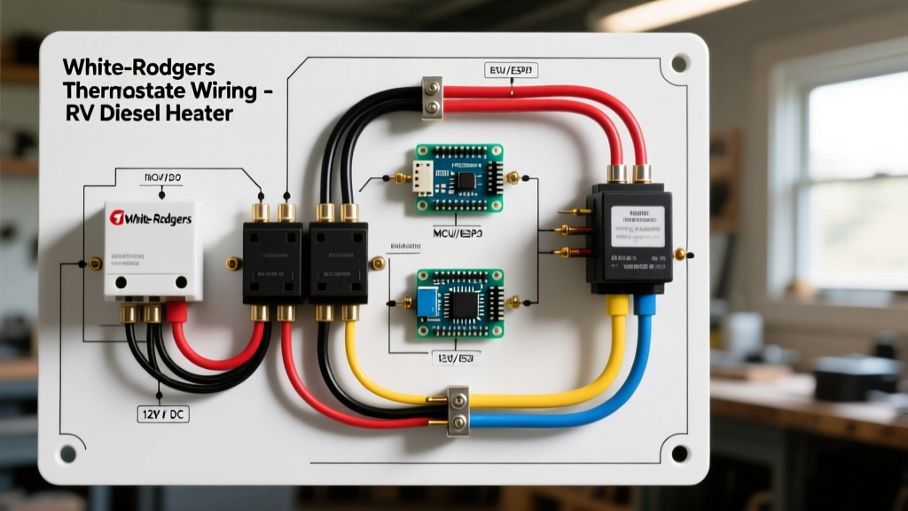
In this scenario, we are wiring a White-Rodgers 110-115 (configured as Normally Closed for a heat call) to activate a 12V DC circulation pump when the vehicle's engine block or cabin heater core drops below 60°F. This is a common setup for maintaining engine warmth in sub-zero expedition environments.
Required Components & Materials
- Thermostat: White-Rodgers 110-115 (SPDT, 60°F set point)
- Relay: 12V DC 30A Bosch-style automotive relay (5-pin)
- Wire: 12 AWG stranded copper (red for power, black for ground)
- Protection: 10A inline ATC fuse holder
- Snubber: 1000µF 25V electrolytic capacitor (critical for inductive loads)
- Terminals: #8 heat-shrink ring terminals
Wiring Procedure
- Establish the Control Power Feed: Run a 12 AWG red wire from your vehicle's 12V DC distribution bus (e.g., Victron Lynx distributor). Install the 10A inline fuse within 6 inches of the busbar. Route this fused 12V+ wire to the Common (C) terminal on the White-Rodgers thermostat.
- Wire the Thermostat Output: Connect a 12 AWG red wire from the Normally Closed (NC) terminal on the thermostat to Pin 86 on the Bosch relay. (When the temperature drops below 60°F, the snap-disc closes the C-to-NC circuit, sending 12V to the relay coil).
- Ground the Relay Coil: Run a 12 AWG black wire from Pin 85 on the relay to a clean, bare-metal chassis ground or your main negative busbar.
- Install the Snubber Capacitor: Solder the 1000µF capacitor directly across Pins 85 and 86 on the relay. Note: Ensure the capacitor's negative stripe points toward Pin 85 (Ground). This absorbs the inductive voltage spike generated when the thermostat's snap-disc opens, preventing micro-arcing that will eventually pit and destroy the White-Rodgers contacts.
- Wire the High-Current Load: Run a heavy 12 AWG (or 10 AWG for long runs) red wire from your main battery positive (or high-amperage busbar) to Pin 30 on the relay. Connect Pin 87 to the positive terminal of your 12V DC circulation pump. Ground the pump directly to the chassis.
Terminal Reference Matrix for Vehicle Integrations
The following table maps the White-Rodgers SPDT terminals to specific vehicle climate applications. Understanding the difference between a heat call and a cool call is vital for mobile HVAC logic.
| WR Terminal | Electrical State (Pre-Setpoint) | Electrical State (Post-Setpoint) | Best Vehicle Application |
|---|---|---|---|
| Common (C) | 12V DC Input / 120V AC Line | 12V DC Input / 120V AC Line | Main power feed from fused busbar |
| Normally Closed (NC) | Continuity with C | Open Circuit | Engine block heaters, Diesel heater pumps (Heat Call) |
| Normally Open (NO) | Open Circuit | Continuity with C | 12V DC exhaust fans, Roof AC compressors (Cool Call) |
120V AC RV Air Conditioner Wiring Guide
For 120V AC applications, such as wiring a White-Rodgers 5D20 capillary thermostat to control a rooftop Dometic or Coleman Mach RV air conditioner, the wiring topology shifts to standard line-voltage practices. According to the NFPA 1192 Standard on Recreational Vehicles, all 120V AC mobile wiring must utilize stranded copper wire with appropriate UV and vibration-resistant insulation (e.g., THHN in flexible conduit or marine-grade triplex).
Wire the 120V AC Hot (Black) to the Common (C) terminal. Wire the Normally Open (NO) terminal to the AC unit's compressor contactor coil or blower motor relay. The Neutral (White) and Ground (Green/Bare) bypass the thermostat entirely, routing directly to the appliance. Always use 14 AWG wire for 15A circuits and 12 AWG for 20A circuits, securing the wires with nylon cable clamps every 18 inches to prevent chafing against the vehicle's aluminum framing.
Troubleshooting Common Mobile Vibration & Voltage Drop Issues
Even with a perfect wiring diagram for a White-Rodgers thermostat, the harsh reality of vehicle dynamics can introduce electrical gremlins. Here is how to diagnose and resolve the most common mobile-specific failures:
1. Contact Chatter and Rapid Cycling
Symptom: The relay clicks rapidly on and off when the vehicle is idling or driving over rough terrain, causing the 12V pump to stutter.
Cause: High-frequency vibration is momentarily separating the snap-disc contacts inside the thermostat.
Fix: Mount the White-Rodgers thermostat using a neoprene isolation pad or rubber grommets to decouple it from the vehicle chassis. If the issue persists, increase the snubber capacitor on the relay coil to 2200µF to provide a longer voltage hold-up during micro-second contact separations.
2. Severe Voltage Drop in Long Wheelbase Vans
Symptom: The thermostat is located in the rear of a 170-inch wheelbase Sprinter van, but the 12V relay and battery are in the front. The pump fails to trigger, or the relay barely engages.
Cause: Running 14 AWG wire over 35+ feet results in a voltage drop exceeding 3%, starving the relay coil of the minimum 9V required to pull the contactor closed.
Fix: Upsize the control wiring from the thermostat to the relay to 10 AWG stranded copper. The Recreational Vehicle Industry Association (RVIA) strongly recommends oversizing wire runs in motorized RVs to account for both voltage drop and the thermal derating of wires bundled inside insulated walls.
3. Capillary Tube Kinking
Symptom: The 5D20 capillary thermostat fails to read the correct temperature in the RV fridge compartment.
Cause: The copper capillary tube was bent at a sharp 90-degree angle during installation behind the cabinetry, restricting the internal fluid expansion.
Fix: Maintain a minimum bend radius of 2 inches for all White-Rodgers capillary tubes. Secure the sensing bulb to the evaporator fin using a dedicated copper or aluminum retaining clip, applying a dab of thermal paste between the bulb and the fin to ensure rapid thermal transfer in a vibrating environment.
Final Compliance & Safety Standards
Integrating commercial components into mobile platforms requires strict adherence to safety standards. Always ensure your 12V DC circuits are protected by Class T or ANL fuses at the battery source, and ATC blade fuses at the branch distribution points. For 120V AC systems, ensure the White-Rodgers thermostat is housed in a sealed, UL-listed junction box to prevent accidental contact with line voltage, especially in the high-humidity environment of an RV bathroom or kitchen. By following these vehicle-specific wiring protocols, you leverage the legendary durability of Sensata's White-Rodgers engineering to build a climate control system that will outlast the vehicle itself.