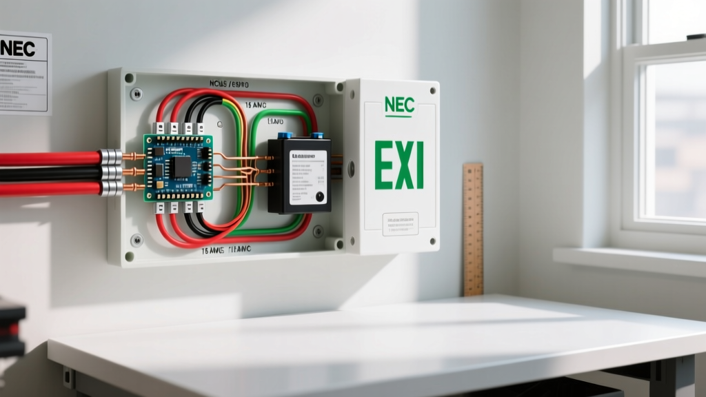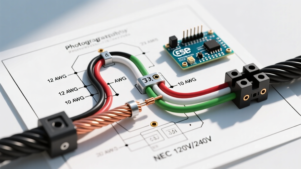

Decoding the Wiring Diagram for Pool Pump Installations
Interpreting a wiring diagram for pool pump systems requires more than just matching colors; it demands a strict adherence to the National Electrical Code (NEC) Article 680, which governs swimming pools, fountains, and similar installations. As of 2026, with the Department of Energy's stringent mandates on variable speed pool pumps (VSPs), the electrical infrastructure supporting these motors must handle complex digital communication lines alongside high-amperage power feeds. A standard residential pool pump draws anywhere from 10 to 16 amps on a 240V circuit, but voltage drop over long conduit runs from the main panel to the pool equipment pad can severely degrade motor lifespan and trip sensitive GFCI breakers. This guide provides the exact wire gauge matrices, THWN color code standards, and termination torque specifications required for a safe, code-compliant installation.
Motor Lead Configurations: 120V vs. 240V Single and Dual Speed
The internal wiring diagram for pool pump motors typically features a terminal board with numbered T-leads (T1 through T8) and a ground screw. While modern variable speed pumps utilize internal solid-state rectifiers that simplify external wiring, traditional single-speed and dual-speed induction motors require manual voltage configuration.
Configuring the T-Leads for 240V Operation
Most residential pools in North America utilize 240V circuits to halve the amperage draw and minimize voltage drop. For a standard 1.5 HP Hayward Super Pump or Century A.O. Smith motor wired for 240V:
- T1, T2, T3, and T8 are typically spliced together and insulated with a wire nut inside the motor peckerhead.
- Line 1 (L1) from the breaker connects to T4.
- Line 2 (L2) from the breaker connects to T5.
- Equipment Ground connects to the green grounding screw on the motor housing and the internal ground lug.
Note: Always verify the schematic glued to the inside of the motor peckerhead cover. Manufacturer revisions frequently alter T-lead numbering schemes.
Configuring for 120V Operation
If your equipment pad is fed by a 120V circuit (common in older installations or specific above-ground pool setups), the wiring diagram for the pool pump changes drastically:
- T2, T3, and T8 are grouped with the White (Neutral) supply wire.
- T1, T4, and T5 are grouped with the Black (Hot) supply wire.
- Line 1 (L1) connects to the grouped T1/T4/T5 bundle.
NEC-Compliant Wire Gauge Sizing Matrix
Selecting the correct wire gauge is critical. NEC Article 680.21 requires branch-circuit conductors to be sized based on the motor's Full Load Amps (FLA) and the specific overcurrent protection device. Furthermore, you must calculate voltage drop. A 3% maximum voltage drop is the industry standard for motor longevity. Below is the 2026 reference matrix for copper THWN-2 conductors in wet locations.
| Motor HP | Voltage | Approx. FLA | Max Breaker Size | Min. Wire Gauge (Up to 50ft) | Min. Wire Gauge (50ft - 100ft) |
|---|---|---|---|---|---|
| 1.0 HP | 240V | 7.5A | 20A (GFCI) | 12 AWG | 10 AWG |
| 1.5 HP | 240V | 9.3A | 20A (GFCI) | 12 AWG | 10 AWG |
| 2.0 HP | 240V | 12.0A | 20A (GFCI) | 10 AWG | 8 AWG |
| 3.0 HP (VSP) | 240V | 16.0A | 40A (GFCI) | 10 AWG | 8 AWG |
2026 Pricing Context: As of early 2026, 10 AWG THWN-2 stranded copper wire averages $0.95 to $1.15 per foot, while 8 AWG hovers around $1.40 per foot. Always purchase stranded wire for conduit pulls; solid wire is prone to snapping under tension when navigating conduit sweeps.
THWN Color Code Standards for Pool Feeders
When pulling individual conductors through PVC or Liquid-Tight Flexible Metallic Conduit (LFMC) to the pool pad, you must adhere to strict NEC color coding. Unlike standard indoor NM-B (Romex) cable, outdoor wet-location wiring utilizes individual THWN-2 or XHHW-2 conductors.
240V Circuit Color Codes (No Neutral Required)
Standard single-speed and most variable speed pool pumps operate on a 240V split-phase circuit and do not require a neutral conductor. The required colors are:
- Black: Line 1 (Hot)
- Red: Line 2 (Hot)
- Green (Insulated): Equipment Grounding Conductor (EGC)
CRITICAL NEC WARNING: According to NFPA 70 (NEC) Article 680.21(A)(3), the equipment grounding conductor for pool motors MUST be an insulated copper conductor with a green outer finish. Bare copper ground wires are strictly prohibited in pool feeder conduits due to the risk of galvanic corrosion and stray voltage in wet environments.
120V Circuit Color Codes
If wiring a 120V pump, a neutral is required for the control circuitry in some older timer setups, though the motor itself only uses Hot, Neutral, and Ground.
- Black: Line 1 (Hot)
- White: Neutral
- Green (Insulated): Equipment Grounding Conductor
Variable Speed Pump (VSP) Control and Communication Wiring
Modern pool automation relies heavily on Variable Speed Pumps like the Pentair IntelliFlo VSF. The power wiring diagram for these pumps is straightforward (L1, L2, Ground), but the low-voltage communication wiring requires specialized attention.
RS-485 Communication Bus
To integrate the VSP with an automation panel (e.g., Pentair IntelliCenter or Hayward OmniLogic), you must run a low-voltage communication cable.
- Cable Type: Use a minimum 18 AWG, 2-conductor shielded twisted pair cable (e.g., Belden 9842 or equivalent RS-485 rated cable).
- Routing: NEC requires low-voltage communication cables to be separated from high-voltage power conduits by at least 6 inches to prevent electromagnetic interference (EMI), which can cause the pump to drop offline or display 'Comm Error' codes.
- Termination: Strip exactly 1/4 inch of insulation. Ensure the drain wire (shield) is properly terminated at the automation panel's ground bus to prevent ground loops, but leave it unterminated at the pump drive end to avoid creating an antenna for EMI.
Conduit, Terminations, and Torque Specifications
The physical execution of the wiring diagram is where most DIY installations fail inspection or suffer premature failure. Pool environments are highly corrosive due to chlorine off-gassing and saltwater splash zones.
Conduit Selection
Never use standard indoor flexible metal conduit. You must use Schedule 40 or 80 PVC conduit, or Liquid-Tight Flexible Metallic Conduit (LFMC) with non-metallic fittings for the final connection to the motor. If using PVC, ensure all joints are primed and glued with wet-location rated cement. For the final 3 feet connecting to the pump, LFMC prevents vibration from cracking rigid PVC joints.
Termination and Anti-Oxidant Paste
When terminating stranded THWN wire into the pump's peckerhead or the GFCI breaker lugs:
- Use a calibrated wire stripper to avoid nicking the copper strands, which creates a localized hot spot.
- Apply a thin layer of Noalox or equivalent anti-oxidant compound to the stripped copper before inserting it into the lug. This prevents aluminum/copper galvanic reactions if the lug is aluminum-rated.
- Torque to Spec: Use an insulated torque screwdriver. Most pool pump terminal blocks require between 12 and 15 in-lbs of torque. Under-torquing leads to arcing and melted terminal blocks; over-torquing strips the brass threads or shears the stranded wire.
Troubleshooting Common Wiring Failure Modes
Even with a perfect wiring diagram for your pool pump, environmental factors can introduce faults. Here are the most common failure modes encountered by electrical troubleshooters:
- Nuisance GFCI Tripping: If a 240V 20A GFCI breaker trips immediately upon startup, check for a neutral-to-ground bond in the pool subpanel or equipment pad. Pool motors do not use a neutral; if a white wire is mistakenly used as a hot and bonded to ground at the motor, the GFCI will detect the imbalance and trip.
- Motor Humming but Not Starting: This usually indicates a failed start capacitor, but it can also be caused by a loose T-lead connection inside the peckerhead. If L1 is connected to T4 but the internal splice to T1/T5 is loose, the motor receives single-phase power and cannot generate starting torque.
- VSP Display Flickering/Resetting: Often misdiagnosed as a bad drive board, this is frequently caused by severe voltage drop due to undersized wire over a long distance (e.g., using 12 AWG wire for a 100-foot run to a 3 HP pump). The inrush current pulls the voltage below the drive's operational threshold, causing a reboot loop.
Frequently Asked Questions
Can I use Romex (NM-B) to wire my pool pump outdoors?
No. NM-B cable is strictly rated for dry, indoor locations. The paper wrapping inside Romex absorbs moisture, leading to rapid insulation breakdown and short circuits. You must use individual THWN-2 or XHHW-2 conductors pulled through a rated outdoor conduit (PVC or LFMC).
Does a pool pump require a GFCI breaker in 2026?
Yes. NEC Article 680.22(C) mandates that all 15A and 20A, 125V or 240V, single-phase receptacles and hardwired pool pump motors must be protected by a Class A Ground-Fault Circuit Interrupter (GFCI). Standard breakers are no longer code-compliant for pool pump circuits.
How do I reverse the rotation of my pool pump motor?
If the pump is moving water but the pressure is extremely low and the motor sounds unusually quiet, it may be spinning in reverse (common on 3-phase commercial pumps, rare on single-phase residential). For single-phase motors, swapping L1 and L2 at the breaker will NOT reverse the motor. You must open the peckerhead and swap the start winding leads (typically T5 and T8) relative to the run winding, as dictated by the specific manufacturer's rotation diagram.