
Bridging Low-Voltage Logic and High-Current Breaker Panels
When building, upgrading, or repairing a high-performance electric scooter, most DIYers focus entirely on the battery and motor. However, the intersection of the electric scooter throttle wiring diagram and the main DC breaker panel is where true system reliability is determined. A throttle operates on delicate 5V Hall-effect logic, while the main power panel handles 48V to 72V at continuous currents exceeding 40 amps. If these two domains are not properly isolated and protected, a simple throttle signal wire short can result in catastrophic controller failure or uncontrolled acceleration.
In this comprehensive 2026 guide, we approach the electric scooter throttle wiring diagram from a Panel & Breaker Guide perspective. We will detail the exact pinouts, wire gauge requirements, DC breaker sizing for the main controller feed, and the critical fault-prevention strategies that separate amateur builds from professional EV engineering.
Anatomy of the Electric Scooter Throttle Wiring Diagram
Modern electric scooters utilize 3-wire Hall-effect twist or thumb throttles. Unlike older potentiometer-based throttles that suffered from physical wear and resistance drift, Hall-effect throttles use magnetic fields to output a precise analog voltage signal to the motor controller (such as a Kelly KLS-7218S or Sabvoton 72V unit).
Standard 3-Pin JST-SM Pinout
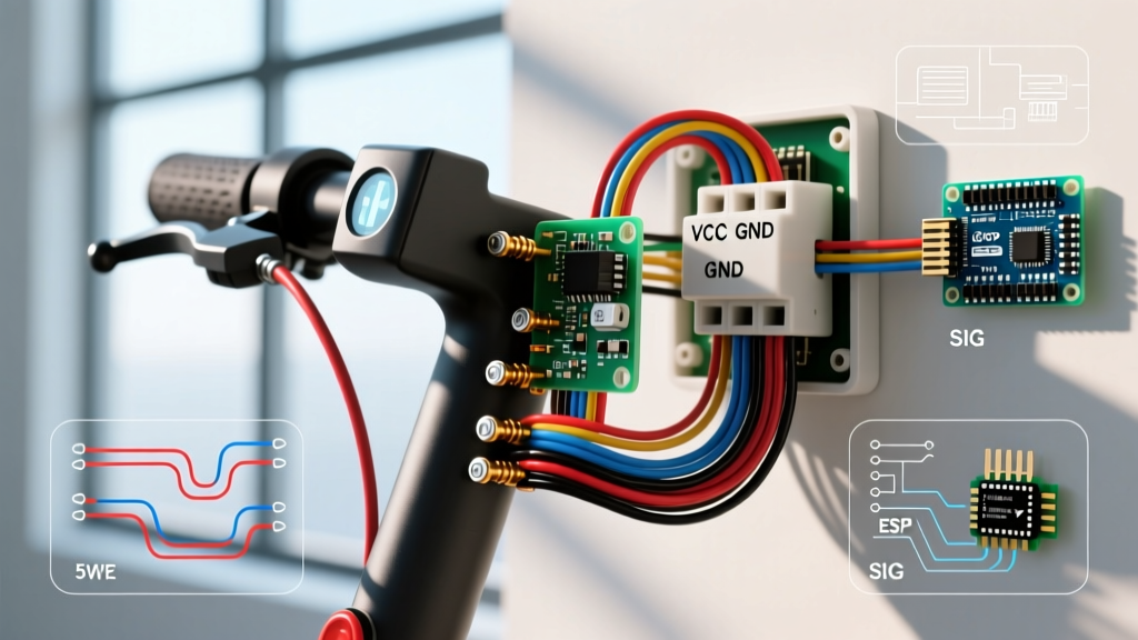
The universal electric scooter throttle wiring diagram relies on a 3-pin connector. While wire colors can occasionally vary by manufacturer (like QS Motor or Votol), the standard configuration is:
- Red Wire (VCC): +5V DC power supplied by the controller’s internal voltage regulator.
- Black Wire (GND): Signal ground, tied to the controller's low-voltage ground plane.
- Green or White Wire (Signal): Analog output voltage. Typically sweeps from 0.8V (resting) to 3.6V or 4.2V (full acceleration).
Expert Warning: Never connect the 5V VCC wire directly to your scooter's 12V accessory panel or DC-DC converter. Doing so will instantly fry the internal Hall sensor IC, costing you a $15 throttle and potentially back-feeding voltage into the controller's logic board.
The Breaker Panel: Protecting the Controller and Throttle Circuit
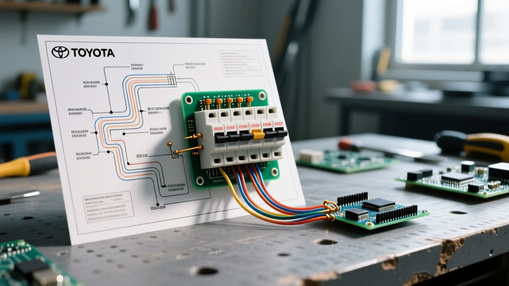
Why does a low-voltage throttle wiring diagram matter to a high-voltage breaker panel? Because the controller acts as the bridge. If the controller's internal 5V regulator fails and leaks 72V battery voltage into the 5V throttle circuit, the throttle will melt, potentially causing a short that keeps the motor engaged. The main DC breaker panel is your last line of defense.
Sizing the Main DC Breaker
According to best practices for DC overcurrent protection, you must size your breaker based on the controller's continuous current rating, not its peak burst rating, while accounting for DC arc quenching. AC breakers must never be used in a scooter's DC panel, as they lack the magnetic blowout mechanisms required to extinguish high-voltage DC arcs, leading to panel fires.
For a standard 1500W, 48V electric scooter setup drawing roughly 35A continuously, a 50A DC-rated breaker (such as a Bussmann ANL or Littelfuse Mega fuse with an inline marine breaker) is optimal. You can review the engineering standards for DC overcurrent protection via resources like Littelfuse's DC fuse guidelines, which emphasize the necessity of rapid arc suppression in battery-driven systems.
Wire Gauge & Routing Matrix
Proper wire sizing prevents voltage drop that can corrupt the 5V throttle signal, while proper routing prevents Electromagnetic Interference (EMI) from the high-current phase wires. Use the following matrix for your panel and throttle integration:
| Circuit Segment | Recommended Wire Gauge | Insulation Type | Breaker/Fuse Sizing |
|---|---|---|---|
| Battery to Main Breaker Panel | 8 AWG or 6 AWG | Silicone (High Temp) | 50A - 80A DC Breaker |
| Breaker Panel to Controller B+ / B- | 8 AWG | Silicone | Protected by Main Breaker |
| Controller 5V to Throttle (VCC/GND) | 22 AWG to 18 AWG | PVC / Shielded | 1A Inline Glass Fuse (Optional) |
| Throttle Signal to Controller | 22 AWG (Shielded) | Foil Shielded PVC | N/A (Logic Level) |
Step-by-Step Panel & Throttle Integration Flow
To ensure your electric scooter throttle wiring diagram translates into a safe, physical build, follow this exact integration sequence:
- Mount the DC Breaker Panel: Secure a marine-grade DC breaker box near the battery terminals. Ensure the negative busbar is bonded to the chassis or main battery ground with at least 10 AWG wire to prevent ground potential differences.
- Install the Pre-Charge Circuit: Wire a 150-ohm 5W pre-charge resistor in parallel with your main contactor or ignition switch. This prevents the massive inrush current from blowing your main DC breaker when the controller's capacitors charge.
- Route the Throttle Harness: Run the throttle's 3-wire harness along the opposite side of the scooter's steering stem from the motor's phase wires (Yellow, Green, Blue). Phase wires carry high-frequency PWM signals that will induce phantom voltages in unshielded throttle wires.
- Terminate with Ferrules: When landing the main power wires into the breaker panel and controller terminals, crimp copper ferrule ends. Stranded wire splayed under a screw terminal creates high-resistance hot spots that will melt the panel housing.
- Verify Logic Voltages: Before connecting the motor, power the panel. Use a multimeter to verify exactly 4.9V to 5.1V at the throttle connector's VCC and GND pins.
Advanced Troubleshooting: Failure Modes and Edge Cases
Even with a perfect wiring diagram, environmental factors and component degradation can cause issues. Here is how to diagnose the most common throttle and panel faults using a standard digital multimeter (like the Fluke 115).
1. Phantom Acceleration (Runaway Throttle)
The Symptom: The scooter accelerates without twisting the throttle, or the motor pulses erratically at idle.
The Cause: EMI interference from the motor phase wires inducing a false voltage on the throttle signal wire, OR a floating ground on the main breaker panel causing a ground loop.
The Fix: Test the signal wire voltage at idle. It should read a rock-solid 0.8V to 0.9V. If it fluctuates between 1.0V and 1.5V, you have EMI ingress. Wrap the throttle signal wire in copper foil tape and ground the drain wire to the controller's logic ground, not the main chassis ground. The principles of Hall-effect sensor shielding are deeply detailed in engineering resources such as All About Circuits' guide on Hall-effect sensors.
2. Dead Throttle with Full Dashboard Power
The Symptom: The dashboard turns on, but the motor does not engage when the throttle is twisted.
The Cause: The controller's internal 5V regulator has failed, or the main DC breaker has tripped due to a micro-short in the throttle harness rubbing against the steering column.
The Fix: Measure the voltage between the Red (VCC) and Black (GND) wires at the throttle plug. If it reads 0V, check the 1A inline logic fuse (if installed) or inspect the controller's 5V output. If the 5V rail is dead, the controller's linear regulator is likely fried and requires board-level repair or replacement.
3. Voltage Sag Under Heavy Load
The Symptom: Throttle response feels 'mushy' or cuts out entirely when climbing hills.
The Cause: Undersized wiring between the battery, the breaker panel, and the controller causing severe voltage sag. If the main battery voltage drops below the controller's Low Voltage Cutoff (LVC), it will shut off the 5V logic rail to protect the battery cells from over-discharge, killing the throttle signal.
The Fix: Monitor the main panel busbar voltage under load. If it drops more than 3V from resting state at full throttle, upgrade your battery-to-panel wiring from 8 AWG to 6 AWG silicone wire and ensure all breaker terminals are torqued to 4 Nm to minimize contact resistance. For more on lithium-ion voltage sag and wiring concerns, consult Battery University's guidelines on Li-ion wiring and load concerns.
Final Safety Directives for Custom EV Builds
Integrating an electric scooter throttle wiring diagram into a custom breaker panel requires respecting the boundary between high-current power distribution and low-voltage logic signaling. Always utilize DC-specific overcurrent protection, maintain strict physical separation between phase wires and signal wires, and verify your 5V logic rail before applying main traction power. By treating the throttle circuit and the breaker panel as a unified safety system, you ensure a responsive, reliable, and fire-safe electric vehicle for years of daily riding.