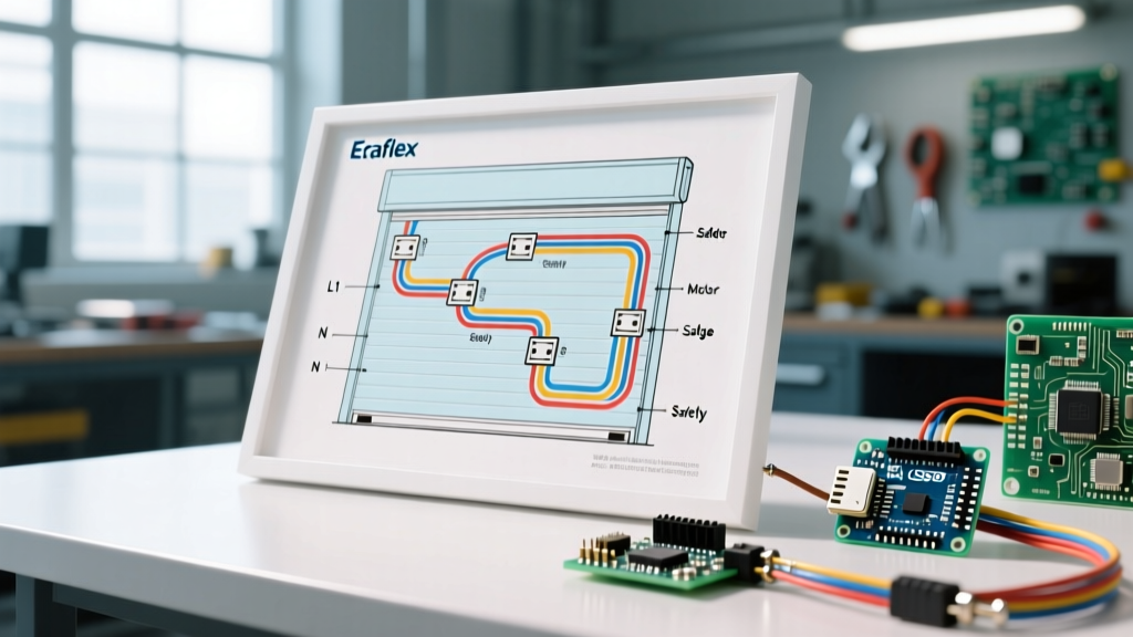

Mastering the Efaflex Roller Shutter Door Electrical Wiring Diagram for Troubleshooting
In 2026, high-speed industrial doors are critical chokepoints in logistics, manufacturing, and cold-storage facilities. When an EFAFLEX high-speed door (such as the EFA-SRT® spiral or EFA-STT® tunnel models) goes offline, downtime costs can easily exceed $5,000 per hour in high-throughput environments. While the proprietary EFA-CON control cabinets are remarkably reliable, they are complex ecosystems integrating 400V 3-phase drives, 24VDC logic networks, and stringent safety circuits. To diagnose faults accurately, a technician must move beyond basic visual inspections and leverage the efaflex roller shutter door electrical wiring diagram as a systematic diagnostic map.
This guide bypasses generic advice and dives deep into the specific architecture of EFAFLEX control panels, providing actionable, diagram-driven troubleshooting workflows for the most common field failures.
Anatomy of the EFA-CON Control Cabinet
Before tracing wires, you must understand the power flow and logic segmentation within the cabinet. Modern EFAFLEX systems typically segment their electrical architecture into three distinct zones, all clearly delineated on the schematic:
- High-Voltage Power & Drive (400V AC): Enters via the main rotary disconnect switch, passes through line reactors or EMC filters, and terminates at the frequency inverter (often a SEW Eurodrive MOVITRAC or Danfoss VLT AutomationDrive). This section powers the main asynchronous or synchronous servo motor.
- Control & Logic Power (230V AC to 24V DC): A step-down transformer drops the voltage to 230V AC for the cabinet cooling fan and brake contactor, while a switched-mode power supply (e.g., Phoenix Contact QUINT) rectifies it to a stable 24V DC for the PLC, HMI touch panel, and I/O modules.
- Safety & Sensor Network (24V DC & 8.2kΩ): This includes the Pilz PNOZ safety relays, through-beam photocells (Sick or Wenglor), and the dynamic 8.2kΩ resistive safety edges embedded in the bottom rubber seal of the door curtain.
Decoding the Diagram: Terminals and Color Standards
When you open the physical efaflex roller shutter door electrical wiring diagram (usually stored in the plastic pouch inside the cabinet door), you will notice strict adherence to IEC 60207 and DIN VDE 0815 color standards. Recognizing these instantly speeds up multimeter probing:
- Black: 400V AC (3-phase motor and main supply)
- Red: 230V AC (Control circuits, brake coils)
- Blue: 24V DC (Logic, sensors, safety relay outputs)
- Yellow/Green: Protective Earth (PE) and shield grounding
- White/Grey: Analog signals or encoder feedback lines
Terminal strips are typically labeled with an 'X' prefix. X1 and X2 are usually reserved for high-voltage power and motor outputs, while X10 through X15 handle low-voltage digital I/O, limit switches, and safety edge inputs. Always verify the terminal block numbering on the physical rail against the schematic, as field modifications during annual maintenance can shift wire positions.
Scenario 1: The 'Ghost' Reversal (Safety Edge Faults)
The Symptom: The door closes smoothly but abruptly reverses when it is 10 to 20 centimeters from the floor, even when no physical obstacle is present. The HMI displays a generic 'Safety Edge Triggered' fault.
The Diagram Trace: Locate the safety edge input on the wiring diagram. The bottom edge of an EFAFLEX door contains a conductive rubber profile wired in a closed-loop circuit with an 8.2kΩ (8k2) resistor. This loop travels up the door column via a coiled spiral cable and terminates at the Pilz safety relay module in the cabinet (typically terminals X12:1 and X12:2).
Troubleshooting Steps:
- Put the system in manual mode and lock out the main drive power.
- Disconnect the spiral cable connector at the base of the door column.
- Using a digital multimeter set to Ohms (Ω), measure across the two pins of the door-side connector.
- Expected Reading: Exactly 8.2kΩ. This confirms the edge and the internal resistor are intact.
- Fault Reading A (OL / Infinite): The spiral cable is internally broken from thousands of extension/retraction cycles, or the rubber edge has been severed. Replace the spiral cable first, as it is the highest-wear component.
- Fault Reading B (Near 0Ω): The safety edge is crushed, or moisture has shorted the conductive rubber profiles together. Inspect the bottom seal for impact damage from forklifts.
Scenario 2: Motor Stalls and Inverter Overcurrent Errors
The Symptom: The door jogs upward a few inches, shudders, and stops. The frequency inverter displays an overcurrent (OC) or position-loss fault code.
The Diagram Trace: Follow the motor power lines (U, V, W) from the inverter output terminals (X2) to the motor terminal box. Next, trace the encoder feedback cable. EFAFLEX systems use absolute encoders (often Hengstler or Heidenhain models) mounted on the motor tail-shaft to track exact curtain position without needing physical limit switches.
Troubleshooting Steps:
- Check the mechanical brake. The diagram shows the brake coil wired to a separate 230V AC contactor. If the contactor engages but the brake rectifier (usually located in the motor terminal box) has failed, the motor will fight the brake, causing an immediate overcurrent trip.
- Inspect the encoder shield grounding. The wiring diagram will explicitly show the encoder cable's metallic shield braid terminating on a copper PE busbar. In 2026, with the prevalence of high-frequency VFD switching, a missing or loose shield ground allows electromagnetic interference (EMI) to corrupt the 24V/5V encoder pulses. If the shield is floating, the PLC loses position tracking and halts the door.
Scenario 3: Complete Logic Blackout (24VDC Failure)
The Symptom: The main 400V disconnect is ON, the cabinet cooling fan is running, but the HMI touch screen is completely black, and the PLC status LEDs are dead.
The Diagram Trace: Trace the control power circuit. Power flows from L1 and L2 (230V AC) into the primary side of the control transformer, passes through a 2A or 4A glass fuse (F1), and into the primary side of the 24VDC power supply.
Troubleshooting Steps:
- Measure the primary side of the 24V power supply. If you read 230V AC but the secondary side reads 0V DC, the power supply unit (e.g., Phoenix Contact QUINT) has failed internally.
- If you read 0V AC on the primary side, check the glass fuse F1. A blown fuse usually indicates a short circuit downstream. Do not simply replace the fuse. Disconnect the 24V load wires (sensors, photocells, solenoid valves) one by one to isolate the short before re-energizing.
Diagnostic Multimeter Reference Chart
Keep this reference matrix handy when probing the terminal blocks identified on your specific wiring schematic.
| Component / Circuit | Terminals (Typical) | Expected Value (Resting) | Fault Indication |
|---|---|---|---|
| Main Power Supply | X1 (L1, L2, L3) | 400V AC (Phase-to-Phase) | <380V indicates supply sag; check utility feed |
| Logic Power Supply | PSU Secondary (+V, -V) | 24.0V - 24.5V DC | <22V DC causes PLC brownouts and relay chatter |
| Bottom Safety Edge | X12:1 to X12:2 | 8.2 kΩ (8,200 Ohms) | OL (broken spiral cable) or <1kΩ (crushed edge) |
| Motor Brake Coil | Brake Contactor Output | 230V AC (when engaged) | 0V AC (failed contactor) or high resistance at coil |
| Photocell (Through-beam) | X14 (Receiver Input) | 24V DC (Clear) / 0V DC (Blocked) | Fluctuating voltage indicates misaligned optics or dirty lens |
Safety and Compliance: Working on High-Speed Doors
Troubleshooting an EFAFLEX door involves working in close proximity to heavy mechanical loads and lethal voltages. As mandated by OSHA Standard 1910.147 for the Control of Hazardous Energy, strict Lockout/Tagout (LOTO) procedures must be applied to the main 400V disconnect before opening terminal covers or probing high-voltage sections.
Furthermore, when testing safety circuits (like the 8k2 edge or photocells), technicians must adhere to the performance levels dictated by machinery safety standards. Bypassing safety relays or shorting out the 8.2kΩ resistor to 'force' a door closed is a severe violation of industrial safety protocols and can result in catastrophic crushing injuries. Always refer to the NFPA 70E standard for proper Arc Flash PPE requirements when taking live voltage measurements on the 400V busbars.
Conclusion
The efaflex roller shutter door electrical wiring diagram is not just an installation guide; it is your most powerful diagnostic instrument. By understanding the segmentation of the EFA-CON cabinet, respecting the IEC color codes, and systematically isolating circuits using a digital multimeter, you can reduce door downtime from hours to minutes. Always prioritize safety, verify your measurements against the schematic, and replace worn components like spiral cables and safety edges with OEM-specified parts to maintain the door's high-speed integrity.