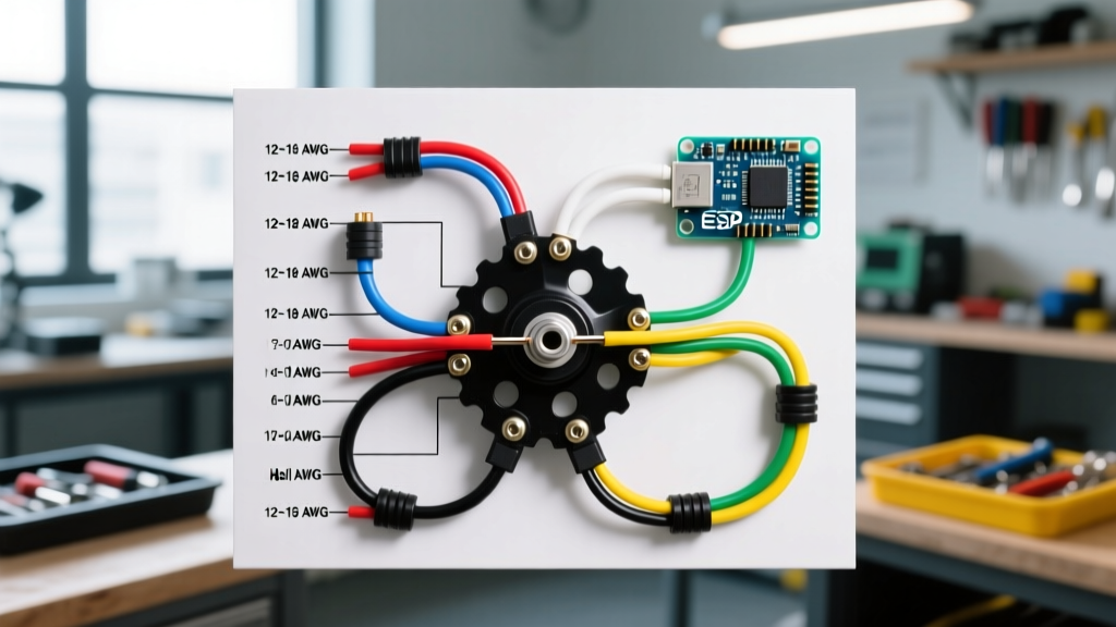

Decoding the Electric Bike Hub Motor Wiring Diagram
When interpreting an electric bike hub motor wiring diagram, the most critical factors for long-term reliability and peak performance are selecting the correct phase wire gauge and strictly adhering to BLDC (Brushless DC) color code standards. As of 2026, the rapid shift toward 72V nominal battery packs and high-discharge 21700 cells means that older, undersized wiring setups are failing at unprecedented rates. Whether you are building a commuter using a Bafang G020 rear hub or a high-power off-road rig with a QS Motor 205mm 50H V4, understanding the exact pinouts and American Wire Gauge (AWG) requirements is non-negotiable.
A standard direct-drive or geared hub motor utilizes two distinct wiring harnesses: the high-current phase wires that drive the stator, and the low-current signal wires (Hall sensors and thermistors) that tell the controller the rotor's exact position and temperature. Misinterpreting either on your electric bike hub motor wiring diagram will result in stuttering, melted connectors, or instantly fried controller logic boards.
Phase Wire Sizing: AWG vs. Peak Current
The three thick phase wires carry the raw amperage from your motor controller to the stator windings. The most common mistake DIY builders make is relying on the manufacturer's pre-installed axle wires, which are often limited to 12 AWG to fit through the hollow motor axle. For controllers pushing over 30A continuous, you must splice to a heavier gauge immediately outside the axle.
According to the Powerstream Wire Size Chart, copper wire current capacity is heavily dependent on the insulation temperature rating. For e-bikes, you must exclusively use stranded silicone wire (rated for 200°C), as standard PVC jacketed wire will melt and short out under the high-heat conditions of a hub motor axle.
Phase Wire Gauge Reference Table
| Wire Gauge (AWG) | Strand Count | Max Continuous Current | Peak Current (10s) | Ideal Connector Type |
|---|---|---|---|---|
| 14 AWG | 400/0.08mm | 15A | 25A | 3.5mm Bullet |
| 12 AWG | 680/0.08mm | 20A | 35A | 4.0mm Bullet |
| 10 AWG | 1050/0.08mm | 35A | 55A | 4.5mm / 5.0mm Bullet |
| 8 AWG | 1500/0.08mm | 50A | 80A | 5.5mm / 6.0mm Bullet |
Note: Always calculate your wire gauge based on the controller's maximum continuous phase current limit, not just the battery's BMS limit.
Standard BLDC Hall Sensor Pinouts & Color Codes
The Hall sensor harness is the nervous system of your hub motor. It typically exits the axle as a 5-pin or 6-pin JST-SM connector. While some manufacturers use proprietary layouts, the industry-standard color code for 95% of hub motors (including Bafang, Leaf Motor, and QS Motor) follows this strict pattern:
- Red: VCC (+5V Power). Critical Warning: Never apply 12V to this wire. It will instantly destroy the internal SS41F Hall IC chips.
- Black: Ground (GND).
- Yellow: Hall Sensor A (Phase A alignment).
- Green: Hall Sensor B (Phase B alignment).
- Blue: Hall Sensor C (Phase C alignment).
Phase Wire Color Mapping
The three phase wires must match the Hall sensor phases for the motor to spin smoothly. The standard mapping is:
- Yellow Phase pairs with Yellow Hall
- Green Phase pairs with Green Hall
- Blue Phase pairs with Blue Hall
If your motor stutters, draws massive current without moving, or spins backward, you have a phase/Hall mismatch. As detailed in eBike School's comprehensive wiring guide, swapping any two phase wires and their corresponding Hall wires will reverse the motor direction, but mixing them randomly will cause a dead short inside the stator.
Thermistor and Speed Sensor Wiring
Modern high-power hub motors include auxiliary wires for thermal protection and speed tracking.
The Thermistor (Temp Sensor)
Usually represented by two white wires (or one white and one black). This is an NTC (Negative Temperature Coefficient) thermistor, typically 10k Ohm at 25°C. It does not have a polarity; you can connect it either way to the controller's temperature input pins. If your controller reads -20°C or 150°C at room temperature, the thermistor wire is either broken or shorted inside the axle.
The Speed Sensor
Often a single white or purple wire bundled with the Halls. This outputs a 5V pulse signal (one pulse per wheel revolution) for your dashboard display. It must be connected to the controller's 'SPD' or 'Speed' pin, never to a power source.
Step-by-Step: High-Current Crimping & Waterproofing
Soldering 8 AWG or 10 AWG silicone wire directly to 5.5mm bullet connectors is a common point of failure. Solder wicks up into the strands, creating a rigid point that snaps under the constant vibration of an e-bike rear triangle. Instead, use a mechanical hex crimp.
- Strip the Wire: Remove exactly 8mm of silicone insulation using a precision wire stripper. Do not nick the copper strands.
- Insert and Crimp: Insert the bare copper into the copper barrel of the bullet connector. Use a dedicated hex-crimp tool (like the IWISS SN-48B with the correct jaw) to apply a uniform 360-degree compression.
- Pull Test: Apply 30 lbs of pull force to ensure the crimp is mechanically sound.
- Adhesive Heat Shrink: Slide a piece of 3:1 ratio dual-wall adhesive heat shrink over the connection. Apply heat until the inner glue layer melts and oozes out the ends, creating a 100% waterproof seal against road salt and rain.
Troubleshooting Common Wiring Failures
Even with a perfect electric bike hub motor wiring diagram, physical failures occur. Here are the most common edge cases:
Failure Mode 1: The 'Melting Axle' Syndrome
Symptom: The motor cuts out under heavy load, and you smell burning plastic near the rear dropout.
Cause: The controller phase current is set higher than the internal 12 AWG motor wires can handle, or the axle nuts were not tightened with serrated washers, causing the motor to spin inside the dropouts and sheer the internal wire insulation.
Fix: Lower the controller's phase current limit by 15%. Install torque arms and ensure serrated drop-out washers are used to ground the axle securely.
Failure Mode 2: Hall Sensor Burnout
Symptom: The motor works perfectly at low speeds but throws an 'Error 07' or Hall fault code when you exceed 25 mph.
Cause: Electromagnetic interference (EMI) from unshielded phase wires running parallel to the Hall sensor cable.
Fix: Separate the phase wires and the Hall sensor cable by at least 4 inches. If they must cross, cross them at a 90-degree angle. Wrap the Hall sensor cable in copper foil tape and ground the tape to the controller chassis.
Frequently Asked Questions
Can I use standard automotive wire instead of silicone wire?
No. Automotive wire uses PVC insulation rated for roughly 105°C. The internal temperature of a hub motor stator under heavy hill-climbing loads can easily exceed 120°C, which will melt PVC insulation and cause a catastrophic phase-to-phase short. Always use high-strand-count silicone wire.
What if my motor has Black, Blue, and Yellow phase wires?
Some older or specific Asian-market motors use Black (Phase A), Blue (Phase B), and Yellow (Phase C). You must map these to your controller's A, B, and C outputs respectively. If the motor stutters, swap Blue and Yellow on both the phase and Hall connections simultaneously.
Do I need to connect the motor thermistor?
For setups under 1000W, it is optional. For any 1500W+ direct-drive hub motor, connecting the thermistor to a compatible controller (like a Phaserunner or Sabvoton) is mandatory. It allows the controller to automatically roll back current when the stator hits 110°C, saving your motor from permanent demagnetization of the neodymium rotor magnets.