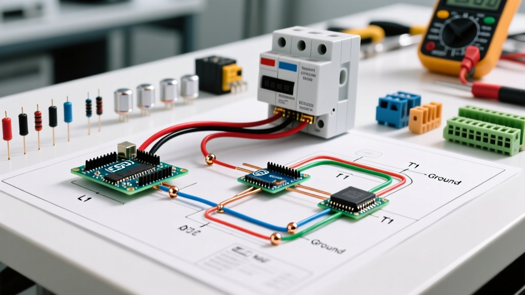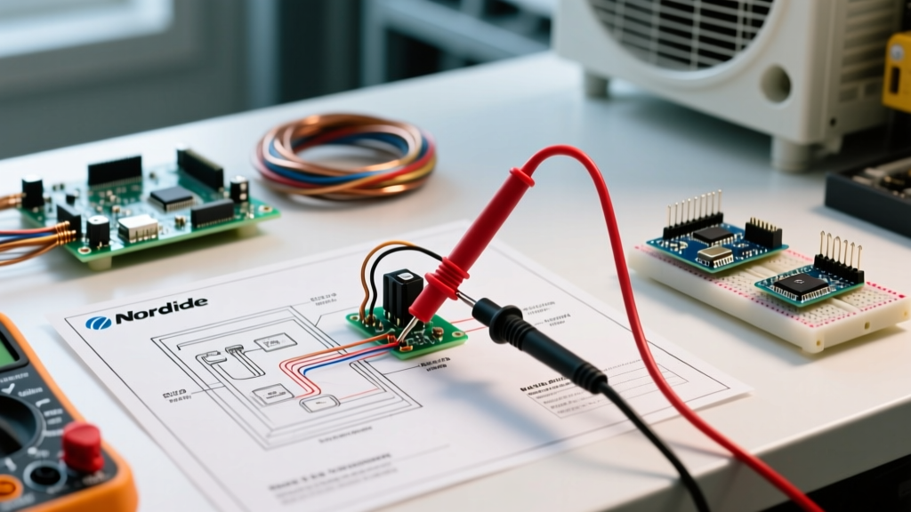

Why Mobile Home Furnace Wiring Requires a Specialized Approach
Troubleshooting HVAC systems in manufactured housing is fundamentally different from standard residential stick-built homes. Mobile home furnaces must comply with strict U.S. Department of Housing and Urban Development (HUD) codes, specifically regarding zero-clearance installation, downflow airflow patterns, and sealed combustion chambers. Nordyne (now operating under Nortek Global HVAC) dominates this sector with its Miller, Intertherm, and standard Nordyne product lines. When a unit fails, guessing the problem leads to wasted money. Utilizing the correct nordyne wiring diagram for mobile home furnace applications is the only reliable way to isolate a failure, whether you are dealing with a legacy Miller M1 series or a modern V5VL high-efficiency downflow unit.
Safety Warning: Mobile home furnaces often integrate 120VAC line voltage and 24VAC control voltage on the same control board. Always disconnect the main breaker and verify zero voltage with a multimeter before opening the blower compartment or touching terminal blocks.
Decoding the Nordyne Control Board Terminals
As of 2026, Nortek has consolidated many legacy Miller and Intertherm control boards into unified Nordyne replacement modules (such as the 903783 and 626604 series). However, the foundational schematic logic remains identical. Before tracing a fault, you must understand the low-voltage terminal designations mapped on your specific diagram.
- R (Red): 24VAC 'Hot' from the step-down transformer. This is your baseline reference voltage.
- C (Blue or Black): 24VAC 'Common'. Completes the circuit for the thermostat and control board logic.
- W (White): Heat call. When the thermostat calls for heat, 24VAC is routed from R to W, signaling the board to initiate the ignition sequence.
- G (Green): Fan call. Energizes the blower motor relay independently of the heating cycle.
- Y (Yellow): Cooling call. Routes 24VAC to the outdoor condenser contactor (if an AC split system is installed).
Diagnostic Troubleshooting Matrix
Use this matrix in conjunction with your schematic to quickly narrow down the root cause of common system failures. This framework prevents the premature replacement of expensive control boards when a simple safety switch has tripped.
| Symptom | Schematic Node to Check | Expected Multimeter Reading | Likely Culprit |
|---|---|---|---|
| Thermostat clicks, but furnace does nothing | R to C terminals on board | 24VAC | Blown 3A ATC automotive fuse on board or failed transformer |
| Inducer motor starts, but no ignition | Pressure Switch (Normally Open) | 0 Ohms (Closed) when inducer runs | Clogged condensate trap, cracked vacuum hose, or failed pressure switch |
| Ignitor glows, but no gas flows | Gas Valve Coil Terminals | 24VAC during trial for ignition | Failed gas valve coil or faulty ignition control module |
| Blower runs continuously, will not shut off | G terminal to C terminal | 0VAC (when thermostat is satisfied) | Welded blower relay on control board or shorted thermostat wire |
| Short cycling (fires for 30 seconds, then dies) | High Limit Switch (Normally Closed) | 0 Ohms (Closed) continuously | Dirty evaporator coil, blocked flue, or failing limit switch bimetal disc |
Step-by-Step Fault Tracing Using the Schematic
Let us apply the wiring diagram to two of the most frequent service calls in manufactured housing: failure to ignite and continuous blower operation.
Scenario A: Inducer Motor Starts, But No Ignition
When you read the nordyne wiring diagram for mobile home furnace ignition sequences, you will notice a strict safety interlock chain. The draft inducer motor must start first to prove a negative pressure draft before the ignitor is allowed to energize.
- Verify the Call for Heat: Set your multimeter to AC Volts. Measure between the W and C terminals. You should read 24VAC. If you read 0VAC, the issue is upstream at the thermostat or the wiring harness.
- Check the Pressure Switch: Locate the pressure switch on the diagram. It is wired in series with the high-limit and rollout switches. Disconnect the two wires from the switch. With the inducer running, place your multimeter probes on the two switch terminals. If it reads infinite ohms (Open), the switch is failing to close. Check the vinyl tubing for micro-cracks or water blockages.
- Test the Hot Surface Ignitor (HSI): If the pressure switch closes, the board sends 120VAC to the HSI. Measure the voltage at the ignitor plug. If 120VAC is present but the ignitor does not glow, unplug it and measure its resistance. A healthy silicon carbide or silicon nitride ignitor should read between 40 and 90 ohms. Infinite ohms means the element is fractured and must be replaced.
Scenario B: Blower Motor Refuses to Shut Off
A blower that runs 24/7 destroys energy efficiency and dries out the indoor air. The wiring diagram shows two distinct pathways that can energize the blower relay: the thermostat 'G' terminal and the fan limit switch.
- Isolate the Thermostat: Remove the 'G' wire from the control board terminal. If the blower stops immediately, the fault lies in the thermostat (likely a stuck mechanical relay or a shorted wire in the wall cavity).
- Check the Fan Limit Switch: If removing the 'G' wire does not stop the blower, the diagram indicates the control board is receiving a closed signal from the fan limit switch located in the heat exchanger plenum. Over time, the bimetal disc inside these switches can weld itself in the closed position due to high-amperage arcing. Replace the limit switch with an exact OEM match (e.g., Cam-Stat or Nordyne specific disc).
- Inspect the Board Relay: If both the 'G' wire and the limit switch are isolated/open, but the blower still runs, the internal blower relay on the control board has mechanically welded its contacts. The entire control board must be replaced.
Essential Multimeter Tests for Nordyne Components
Having a baseline of expected electrical values is critical for rapid diagnosis. Memorize or bookmark these specifications for standard Nordyne/Miller mobile home components:
- High Limit Switch: Normally Closed (NC). Must read 0.1 to 0.5 ohms when cold. If it reads infinite ohms at room temperature, it is internally broken.
- Rollout Switch: Normally Closed (NC). Manually resettable. Reads 0.1 to 0.5 ohms. If tripped, inspect the burner box for rusted heat exchangers causing flame roll-out.
- Gas Valve Coil (Standard 24V): Typically reads between 30 and 50 ohms.
- Gas Valve Coil (Honeywell SmartValve): Reads significantly lower, usually between 1.5 and 5.0 ohms. Do not replace a SmartValve thinking it is shorted just because of the low resistance reading; this is normal for its internal step-down transformer.
- Transformer Primary (120V): Should read 120VAC. Secondary must read 24VAC to 28VAC under no load.
Safety, Compliance, and Authoritative Resources
Working on manufactured home HVAC systems requires strict adherence to federal safety standards. Modifying the wiring to bypass safety switches (like jumpering a rollout switch) is a severe fire hazard and violates federal law. The U.S. Department of Housing and Urban Development (HUD) Manufactured Housing Program strictly mandates that all replacement parts and wiring configurations must match the original design certification to maintain the home's safety rating.
Furthermore, routine maintenance is vital to prevent the very electrical faults detailed in these schematics. According to the U.S. Department of Energy, replacing clogged air filters and ensuring unobstructed return air pathways can prevent the high-limit switches from tripping, saving homeowners from unnecessary service calls and component degradation. For specific schematic PDFs and technical bulletins, technicians should consult the Nortek Global HVAC Nordyne literature portal, which hosts the most up-to-date wiring diagrams and service manuals for all current and legacy mobile home furnace models.
By systematically following the pathways on your Nordyne wiring diagram, verifying voltage at each node, and respecting the unique constraints of manufactured housing, you can accurately diagnose and repair mobile home furnace faults with professional precision.