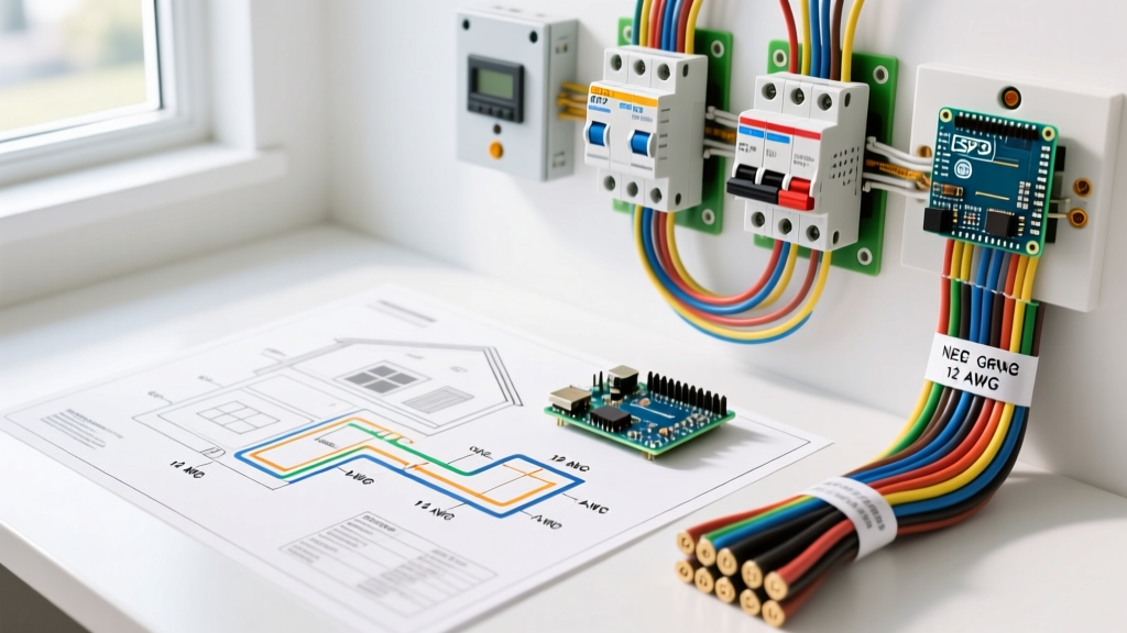

The Critical Role of NEC Compliance in Residential Diagrams
Drafting accurate electrical wiring diagrams residential electricians and inspectors rely on is not just about mapping circuits; it is the foundational blueprint for life safety. In 2026, local jurisdictions across the United States are aggressively adopting the latest iterations of the National Electrical Code (NEC), meaning outdated diagrams that omit modern arc-fault or ground-fault protections will result in immediate inspection failures. According to the National Fire Protection Association (NFPA), electrical malfunctions remain a leading cause of residential fires, making strict adherence to diagrammatic code compliance a non-negotiable standard.
A residential wiring diagram serves as the legal and technical document for your installation. It must clearly delineate load calculations, wire routing, grounding electrode systems, and overcurrent protection device (OCPD) specifications. Failing to represent these elements accurately on paper inevitably leads to dangerous field improvisations.
Decoding Standard Residential Wiring Symbols
Before calculating loads or routing cables, you must standardize your schematic language. Inspectors look for universally recognized symbols that comply with ANSI Y32.9 standards. Below is a reference matrix for critical safety symbols that must appear on your residential plans.
| Symbol | Component Description | NEC Reference / Safety Note |
|---|---|---|
| GFCI | Ground-Fault Circuit Interrupter Receptacle | NEC 210.8(A) - Required in wet/damp locations |
| AFCI | Arc-Fault Circuit Interrupter Breaker | NEC 210.12 - Required in most living spaces |
| Ufer | Concrete-Encased Grounding Electrode | NEC 250.52(A)(3) - Mandatory for new builds |
| WP | Weatherproof / In-Use Cover | NEC 406.9(B)(1) - Required for outdoor 15A/20A |
| SPD | Surge Protective Device (Whole House) | NEC 230.67 - Required for new service upgrades |
Mandatory Safety Circuits: AFCI and GFCI Mapping
The most common reason residential diagrams are rejected during the plan review phase is the improper mapping of AFCI (Arc-Fault Circuit Interrupter) and GFCI (Ground-Fault Circuit Interrupter) protections. As of the latest code cycles, the footprint for these devices has expanded significantly.
GFCI Requirements (NEC Article 210.8)
Your diagram must explicitly mark GFCI protection for all 125-volt through 250-volt receptacles supplied by single-phase branch circuits rated 150 volts or less to ground. This includes kitchens, bathrooms, garages, crawl spaces, unfinished basements, and outdoor areas. For outdoor HVAC equipment, NEC 422.31(B) now frequently requires GFCI protection for the disconnect, which must be reflected on your exterior elevation diagrams.
AFCI Requirements (NEC Article 210.12)
Arc-fault protection is required in almost all habitable rooms, including kitchens, family rooms, dining rooms, living rooms, parlors, libraries, dens, sunrooms, recreation rooms, closets, hallways, and laundry areas. When specifying breakers on your panel schedule diagram, use exact model numbers to prevent contractor substitution errors. For example, specify the Square D HOM120CPFI (Homeline 20A CAFI) or the Eaton BRCAF120 rather than writing a generic '20A AFCI'.
Expert Insight: Dual Function (DF) breakers, which combine both AFCI and GFCI protection in a single device, are highly recommended for kitchen and laundry circuits. Specifying a Square D HOM120DF on your diagram eliminates the need for bulky GFCI receptacles under sinks where space is constrained, reducing installation costs by approximately $15 per circuit while maintaining strict code compliance.
Wire Gauge and Ampacity: Sizing Your Diagram Correctly
Wire sizing is governed by NEC Article 310, specifically table 310.16. A common and dangerous mistake on amateur diagrams is sizing the wire to the load rather than the overcurrent protection device. Your diagram must include a wire gauge legend that correlates the breaker size, conductor material, and insulation temperature rating.
| Breaker Size (OCPD) | Copper Wire Gauge (THHN/THWN-2) | Max Continuous Load (80% Rule) | Typical Residential Application |
|---|---|---|---|
| 15 Amp | 14 AWG | 12 Amps | General lighting, bedroom receptacles |
| 20 Amp | 12 AWG | 16 Amps | Kitchen small appliance, bathroom, laundry |
| 30 Amp | 10 AWG | 24 Amps | Electric water heaters, RV receptacles |
| 40 Amp | 8 AWG | 32 Amps | Electric ranges (specific models), EV chargers |
| 50 Amp | 6 AWG | 40 Amps | Electric ranges, hot tubs, subpanels |
Note: Always calculate voltage drop for runs exceeding 100 feet. If a 12 AWG wire run to a detached garage exceeds 100 feet, your diagram must note an upsizing to 10 AWG to maintain a maximum 3% voltage drop, as recommended by NEC Informational Note 4 to 210.19(A)(1).
Grounding and Bonding: The Backbone of Residential Safety
The terms 'grounding' and 'bonding' are frequently conflated on poorly drafted diagrams, leading to severe inspection violations. Grounding connects the electrical system to the earth (via ground rods or a Ufer ground), while bonding connects all metallic non-current-carrying parts together to ensure a low-impedance fault current path back to the source.
For a standard 200-amp residential service, NEC Article 250.66 mandates a minimum 4 AWG copper or 2 AWG aluminum Grounding Electrode Conductor (GEC). Your main service diagram must explicitly show the GEC routing from the neutral bus bar to the grounding electrode system. Furthermore, the main bonding jumper must be clearly indicated at the service disconnect. In subpanels, the neutral and ground buses must be shown as physically isolated—a critical detail that inspectors verify against your schematic.
Common Diagram Mistakes That Fail Residential Inspections
Even experienced drafters make errors that trigger red tags during the rough-in or final inspection phases. Avoid these specific edge cases:
- Multi-Wire Branch Circuit (MWBC) Omissions: If your diagram shows two 120V circuits sharing a single neutral (MWBC), NEC 210.4(B) requires you to explicitly note the use of a handle-tied or common-trip double-pole breaker (e.g., Square D QO220) to simultaneously disconnect all ungrounded conductors.
- Missing Torque Specifications: NEC 110.14(D) requires that terminations be torqued to manufacturer specifications. Professional diagrams now include a general note specifying the use of a calibrated torque screwdriver (like the Klein Tools 69010, retailing around $120) for all breaker and busbar terminations.
- Improper Bathroom Circuit Mapping: NEC 210.11(C)(3) dictates that the 20-amp bathroom receptacle circuit must serve only bathroom receptacles. It cannot feed lights, fans, or receptacles in other rooms. Your diagram must isolate these loads clearly.
FAQ: Residential Wiring Diagrams and Permitting
Do I need to submit a full wiring diagram for a simple panel upgrade?
Yes. Most municipalities require a single-line diagram showing the service entrance conductors, meter base rating, main breaker size, and the grounding electrode system for any service upgrade, even if branch circuits remain untouched.
Can I use software to generate NEC-compliant diagrams?
Yes, software like AutoCAD Electrical or SmartDraw includes 2026-compliant NEC symbol libraries. However, the software does not calculate load diversity or verify AFCI mapping; the electrical designer must manually apply code logic to the schematic.
For further reading on workplace and residential electrical safety standards, refer to the Occupational Safety and Health Administration (OSHA) Electrical Guidelines and the Consumer Product Safety Commission (CPSC) resources on GFCI and AFCI technologies. Proper diagramming is the first and most vital step in preventing electrical fires and ensuring a safe living environment.