
The Hidden Complexity of Automotive Electrical Schematics
When technicians and DIY enthusiasts first examine wiring diagrams for vehicles, they often focus solely on tracing the path from the power source to the load. However, the true devil is in the details—specifically, the wire gauge annotations and color codes printed alongside those lines. Misinterpreting a wire's cross-sectional area or misidentifying a faded tracer stripe can lead to catastrophic voltage drops, melted harnesses, or intermittent CAN bus failures.
Unlike residential wiring governed by the National Electrical Code (NEC), automotive electrical systems operate under a completely different set of physics and standards. This guide decodes the critical gauge and color code references you need to accurately read, repair, and modify vehicle wiring harnesses in modern 12V and 24V platforms.
The Great Gauge Deception: SAE vs. AWG
One of the most common and costly mistakes made when interpreting American wiring diagrams for vehicles is assuming the wire gauge listed is American Wire Gauge (AWG). In reality, the automotive industry primarily uses the Society of Automotive Engineers (SAE) gauge standard, specifically outlined in the SAE J1128 Standard for Low Tension Cable.
While an 18 AWG wire and an 18 SAE wire sound identical, they are not. SAE wire gauges are physically smaller in cross-sectional area than their AWG counterparts for any given number above 1 AWG. If you replace a blown 14 SAE harness wire with 14 AWG wire, you are actually upsizing. But if a diagram calls for 10 AWG and you install 10 SAE, you are installing a wire with roughly 11% less conductive copper, which can cause premature voltage drop and overheating under high continuous loads like cooling fans or fuel pumps.
Cross-Sectional Area & Ampacity Comparison
Understanding the exact metric equivalents is crucial for cross-referencing American diagrams with European or Asian schematics, which strictly use metric cross-sectional areas (mm²).
| Gauge Size | AWG Area (mm²) | SAE Area (mm²) | Max Ampacity (105°C Insulation) | Common Automotive Application |
|---|---|---|---|---|
| 8 | 8.37 | 8.00 | 73A | Main alternator feed, starter solenoid |
| 10 | 5.26 | 5.00 | 55A | High-amperage cooling fans, ABS modules |
| 12 | 3.31 | 3.00 | 41A | Headlights, power windows, fuel pumps |
| 14 | 2.08 | 2.00 | 32A | Interior lighting, horn, cigarette lighter |
| 16 | 1.31 | 1.30 | 22A | Dashboard illumination, small relays |
| 18 | 0.82 | 0.80 | 16A | Sensors, ECU triggers, low-draw LEDs |
| 20 | 0.52 | 0.50 | 11A | CAN bus lines, data networks, airbag squibs |
Decoding Automotive Wire Color Codes
Wire color codes in vehicles are not universally standardized across all manufacturers, but they generally follow regional frameworks. American vehicles lean heavily on SAE J1128 color conventions, while European vehicles (Volkswagen, BMW, Mercedes-Benz) adhere strictly to DIN 72551. Asian manufacturers (Toyota, Honda) often use a hybrid approach but lean toward metric sizing and specific proprietary color matrices.
The SAE / American Color Matrix
In American schematics, colors are abbreviated using three-letter codes. A solid color is listed first; if the wire has a tracer (a thin stripe spiraling down the insulation), it is listed after a slash or hyphen.
- BLK (Black): Almost universally used for chassis ground in American vehicles.
- RED (Red): Unswitched battery positive (B+). Constant 12V directly from the battery or main fuse box.
- YEL (Yellow): Often used for switched 12V (ignition-on) or high-current accessory feeds.
- ORN (Orange): Commonly used for dashboard illumination circuits or dimmer switches.
- GRN (Green): Frequently assigned to sensor returns, tachometer signals, or emissions solenoids.
- BLU (Blue): Often used for high-beam headlights or specific OEM data lines.
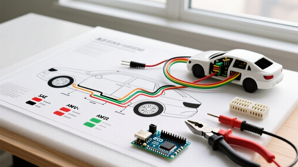
Diagram Example: A line labeled 14 RED/WHT indicates a 14-gauge wire with a Red primary insulation and a White tracer stripe. According to the BulkWire Automotive Color Code Guide, the primary color always makes up at least 70% of the visible surface area.
The DIN 72551 / European Color Matrix
If you are reading wiring diagrams for vehicles manufactured in Europe, you must abandon the American color logic. European diagrams use metric sizes (e.g., 1.5, 2.5) and DIN terminal numbers (Kl. 30, Kl. 15, Kl. 31) paired with specific colors.
Expert Insight: In DIN-standard diagrams, Brown (BR) is always Ground (Terminal 31). Red (RD) is always constant Battery Positive (Terminal 30). Black (BK) is switched ignition power (Terminal 15). Mixing up Black and Brown in a European harness will result in an immediate dead short and blown main fusible link.
Reading Gauge and Size Annotations on Schematics
Automotive wiring diagrams use highly condensed syntax to convey wire size, color, and sometimes even the circuit number. Here is how to parse the most common annotation formats:
Format 1: The American Standard (Gauge + Color)
Example: 16 GRY/BLK
- 16: Wire gauge (SAE).
- GRY: Primary color (Gray).
- BLK: Tracer color (Black).
Format 2: The European/Asian Metric Standard (Area + Color)
Example: 1.5 BR or 0.5 RD/YL
- 1.5 / 0.5: Cross-sectional area in square millimeters (mm²).
- BR / RD: Primary color (Brown / Red).
- YL: Tracer color (Yellow).
Format 3: The Toyota/Lexus Circuit Code
Example: B-Y 18 2A
- B-Y: Color (Black with Yellow tracer).
- 18: Wire gauge.
- 2A: Circuit identifier (helps trace the wire across multiple pages of the service manual without losing the signal path).
Voltage Drop: The Silent Killer in Vehicle Wiring
When modifying or repairing harnesses based on wiring diagrams for vehicles, simply matching the wire gauge is not always enough if you are extending the wire length. Automotive systems operate at a nominal 12.6V (engine off) to 14.4V (engine running). Modern ECUs and sensors will throw diagnostic trouble codes (DTCs) or enter limp mode if voltage drops below 10.5V at the component.
For critical electronics (ECUs, ABS modules, transmission solenoids), the industry standard mandates a maximum voltage drop of 3% (0.36V). For non-critical loads (cigarette lighter sockets, trunk lights), a 5% (0.60V) drop is acceptable.
12V System Wire Sizing Matrix (For 15A Continuous Load)
Use this reference when extending circuits to ensure you do not exceed the 3% voltage drop threshold.
| One-Way Wire Length | Minimum SAE Gauge Required | Minimum Metric (mm²) Required | Expected Voltage Drop |
|---|---|---|---|
| 5 Feet (1.5m) | 16 AWG/SAE | 1.5 mm² | 0.19V (1.5%) |
| 10 Feet (3.0m) | 14 AWG/SAE | 2.0 mm² | 0.31V (2.5%) |
| 15 Feet (4.5m) | 12 AWG/SAE | 3.0 mm² | 0.34V (2.7%) |
| 20 Feet (6.0m) | 10 AWG/SAE | 5.0 mm² | 0.31V (2.5%) |
Insulation Types: TXL, GXL, and HDT
Wiring diagrams rarely specify the insulation thickness, but when sourcing replacement wire for high-heat areas (near exhaust manifolds, turbochargers, or inside engine bays), you must select the correct automotive-grade insulation. Standard PVC hook-up wire will melt and cause a short circuit.
- TXL (Thin Wall): The most common modern automotive wire. Features a thin, tough cross-linked polyethylene (XLPE) insulation. Rated for 125°C. Ideal for tight spaces inside modern, densely packed dashboards.
- GXL (General Purpose): Slightly thicker insulation than TXL, also rated for 125°C. Excellent for general engine bay routing where minor abrasion resistance is needed.
- HDT (Heavy Duty Thermoplastic): Thick PVC insulation. Rated for lower temperatures (105°C) but offers superior physical abrasion resistance. Used in commercial trucks and heavy equipment where wires are routed through metal chassis holes without grommets.
For high-performance applications and OEM replacements, sourcing proper TXL or GXL wire from reputable suppliers like Mouser Electronics' TE Connectivity automotive line ensures the harness can withstand the thermal cycling of modern engine bays.
Troubleshooting Edge Cases in Aging Harnesses
When working on vehicles older than 10 years, the physical wires rarely match the factory wiring diagrams perfectly. Keep these troubleshooting realities in mind:
1. The 'Faded Tracer' Phenomenon
Engine bay heat and oil exposure cause white and yellow tracer stripes to fade or turn completely brown. If you are tracing a RED/WHT wire and it looks solid dark brown, scrape a small window in the insulation or check the wire's cross-section under a magnifying glass to confirm the tracer before splicing.
2. Aftermarket 'Frankenstein' Harnesses
Previous owners frequently use whatever wire is available for repairs. If a diagram calls for a 14-gauge Black ground wire, but you find a 16-gauge Blue wire spliced in with a butt connector, you have found a high-resistance bottleneck. Always perform a voltage drop test across the repaired section (placing your multimeter probes on either side of the splice while the circuit is under load) to verify the repair's integrity.
3. Shielded Data Cables
Modern diagrams will often show a wire enclosed in a dotted line or labeled with a 'SH' (Shield) designation. This indicates a shielded twisted pair used for high-speed CAN bus (CAN-C) or FlexRay networks. Never untwist these wires more than 1 inch (25mm) when repairing, and always reconnect the drain wire to the chassis ground, or the vehicle will experience severe electromagnetic interference (EMI) and network dropouts.
Summary
Mastering wiring diagrams for vehicles requires looking beyond the schematic lines and understanding the physical properties of the wires they represent. By respecting the differences between SAE and AWG gauges, memorizing regional color code matrices, and calculating voltage drop for extended runs, you elevate your automotive electrical work from guesswork to precision engineering.