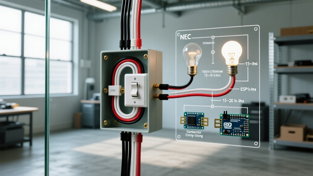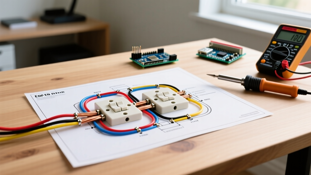

Understanding the 4-Way Switch Circuit Topology
When controlling a single light fixture from three or more locations, standard 3-way switches are not enough. This is where a wiring diagram for 4 way switches becomes essential. A 4-way switch acts as a reversing crossover mechanism placed strictly between two 3-way switches. According to the National Electrical Code (NEC) Article 404, switches must be configured so that they disconnect the ungrounded (hot) conductor, meaning the neutral wire must never be switched or broken at any point in this multi-location setup.
In a standard hallway or large living room application, the circuit topology follows a strict linear path: Power Source → 3-Way Switch → 4-Way Switch → 3-Way Switch → Load (Light Fixture). The 4-way switch does not have a 'common' terminal like its 3-way counterparts. Instead, it features four traveler terminals (usually brass) and one ground terminal (green). Its internal mechanism simply swaps the connection between the two pairs of travelers, reversing the circuit path to complete or break the hot connection to the load.
Core Components and Material Costs
Before pulling any wire, you must gather the correct materials. Using undersized wire or the wrong switch type is a leading cause of tripped breakers and fire hazards. Below is a precise bill of materials for a standard 15-amp residential lighting circuit.
| Component | Specification / Model | Estimated Cost | Purpose |
|---|---|---|---|
| 4-Way Switch | Leviton Decora 5604 (15A) | $12.50 - $15.00 | Crossover mechanism for intermediate locations. |
| 3-Way Switches (x2) | Leviton Decora 5603 (15A) | $10.00 - $13.00 ea. | Line and Load termination points. |
| Traveler Cable | Southwire 14/3 NM-B Romex | $0.75 - $1.10 / ft | Carries travelers and pass-through neutral. |
| Line/Load Cable | Southwire 14/2 NM-B Romex | $0.50 - $0.80 / ft | Source power and switch-leg to fixture. |
| Voltage Tester | Klein Tools NCVT-3 | $35.00 - $40.00 | Dual-range non-contact voltage verification. |
| Wire Connectors | Ideal WireNuts (Tan/Red) | $8.00 / box | Secure splicing of neutral bundles. |
Step-by-Step Wiring Walkthrough
Follow this exact sequence to wire a 3-location circuit. This guide assumes you are installing a new 15-amp circuit or rewiring an existing one with modern NM-B (Romex) cable.
- Step 1: Power Verification and Preparation
Shut off the 15A or 20A breaker at the main panel. Use your Klein NCVT-3 to test the existing wires. Crucial Edge Case: Phantom voltages can sometimes trigger low-sensitivity testers if wires are run parallel in the same conduit. Always verify with a contact multimeter set to AC Voltage if the NCVT gives an ambiguous reading. - Step 2: Wiring the First 3-Way Switch (Line Side)
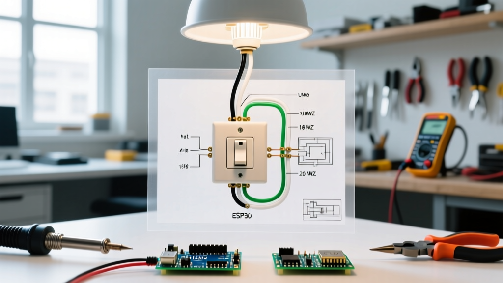
At the first switch box, you will have the incoming 14/2 power cable. Connect the bare copper ground to the green ground screw. Bundle the white neutral wires together with a wire nut and push them to the back of the box (do not connect them to the switch). Connect the black hot wire to the Common (dark-colored) screw on the 3-way switch. - Step 3: Routing the Travelers to the 4-Way
Run a 14/3 NM-B cable from the first 3-way box to the 4-way box. Connect the black and red wires to the two Brass (traveler) screws on the first 3-way switch. Cap the white wire with electrical tape to re-identify it, or simply push it through the box as a continuous neutral pass-through. Pro Tip: Always push the neutral through the 4-way box, even if the current mechanical switch doesn't need it. This future-proofs the box for smart switches. - Step 4: Wiring the 4-Way Switch (The Crossover)
At the intermediate 4-way box, you will have two 14/3 cables entering (one from the first 3-way, one heading to the second 3-way). Connect all bare grounds to the green screw. Bundle all white neutrals together. On the 4-way switch, you will see four brass screws, often grouped in two pairs (sometimes marked 'IN' and 'OUT' or 'LINE' and 'LOAD' by manufacturers like Leviton). Connect the black and red travelers from the first cable to one pair of brass screws, and the black and red travelers from the second cable to the other pair. Never mix the pairs. - Step 5: Wiring the Second 3-Way Switch (Load Side)
At the final box, connect the black and red travelers from the incoming 14/3 cable to the two brass screws on the second 3-way switch. Connect the black wire of the outgoing 14/2 cable (heading to the light fixture) to the Common (dark-colored) screw. Bundle the neutrals and grounds appropriately. - Step 6: Fixture Termination and Testing
At the light fixture, connect the incoming black (switched hot) to the fixture's black wire, white to white, and ground to ground. Restore power at the panel and test all three locations. The light should toggle correctly regardless of the position of the other switches.
2026 Smart Switch Integration: The Neutral Pass-Through
One of the most common mistakes electricians and DIYers make when following a traditional wiring diagram for 4 way switches is failing to carry the neutral wire through the intermediate 4-way switch box. Older wiring diagrams often show the 14/3 cable using the white wire as a third traveler, capping it off at the switches.
In modern electrical design, this is considered obsolete. Smart lighting ecosystems, such as the Leviton Decora Smart or Lutron Caseta lines, require a constant 120V neutral connection at the switch box to power their internal Wi-Fi, Zigbee, or Thread radios. If you omit the neutral pass-through in the 4-way box, you will be forced to tear open drywall to run new cable if you ever decide to upgrade to smart lighting. Always use 14/3 (or 12/3 for 20A circuits) and dedicate the white wire solely as a pass-through neutral, using only the black and red wires as the two travelers.
Troubleshooting Common Failure Modes
If your circuit fails to operate correctly after following the walkthrough, do not start randomly swapping wires. Use a logical diagnostic approach based on the symptoms below.
Symptom: The light only works from one specific switch location.
Diagnosis: You have likely connected the incoming hot or the outgoing load to a traveler (brass) screw instead of the common (dark) screw on one of the 3-way switches. The 4-way switch is functioning correctly, but the 3-way is failing to route power to the traveler pair.
Symptom: The light works from the 3-ways, but the 4-way switch does nothing.
Diagnosis: You have crossed the traveler pairs on the 4-way switch. For example, you connected one traveler from Cable A and one from Cable B to the same 'IN' pair of screws. The crossover mechanism cannot function if the input and output pairs are mixed. Ensure Cable A occupies one distinct pair, and Cable B occupies the other.
Symptom: The breaker trips immediately upon toggling a switch.
Diagnosis: You have created a direct short circuit. This almost always happens when a white neutral wire is accidentally tied to a brass traveler terminal, or when a bare ground wire touches a traveler screw due to an overly tight wall box. Turn off the breaker, pull the switches out, and inspect for pinched wires or stray copper strands.
Final Safety and Code Reminders
Always ensure your wall boxes are rated for the volume of wires they contain. A standard single-gang box (18 cubic inches) is often too small for a 4-way switch box, which may contain two 14/3 cables, a ground bundle, and a neutral bundle. According to NEC Article 314.16 box fill calculations, each 14 AWG wire counts as 2.0 cubic inches. Upgrading to a 22.5 or 25.5 cubic inch 'deep' single-gang box, or using a double-gang box with a single-gang mud ring, will prevent overcrowding, reduce the risk of pinched insulation, and make the physical installation of the switch significantly easier.