
Strategic Planning for Craftsman Mower Electrical Overhauls
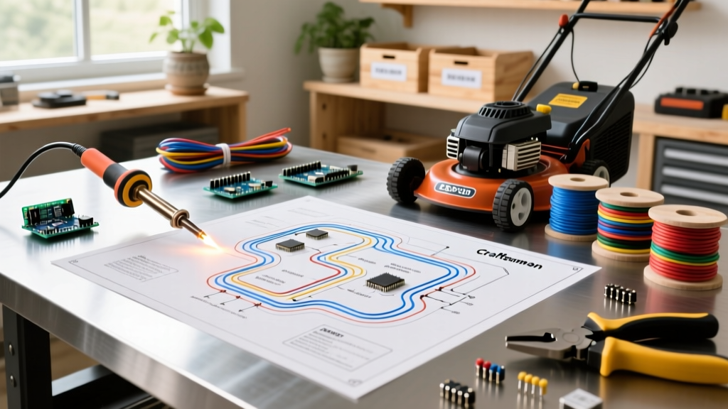
Whether you are restoring a classic Craftsman YT3000, replacing a degraded harness on a T225 (Model 13A722JD091), or integrating high-draw LED work lights, relying on memory or guesswork is a fast track to a melted harness or a dead battery. The wiring diagram for Craftsman riding lawn mower applications is not just a troubleshooting map; it is an essential installation planning document. In 2026, with the rising cost of OEM replacement harnesses (typically ranging from $95 to $165 depending on the chassis), planning your wire routing, gauge, and termination strategy before cutting a single zip-tie is critical for a reliable, fire-safe repair.
This installation planning guide breaks down how to translate the factory schematic into a physical execution plan, ensuring, and test your system before the initial crank.
Decoding the Schematic Blueprint
Before purchasing wire and terminals, you must translate the same terminal designations across almost all Craftsman riding mower schematics produced over the last two decades. Understanding these nodes is crucial for planning your harness routing.
- B (Battery): Receives constant 12V DC from the starter solenoid or battery positive. This is your primary power feed.
- L (Lights): Routes power to the headlight circuit. Usually protected by an inline 15A fuse.
- A (Accessory/Alternator): Receives AC voltage from the stator, which is rectified to DC to charge the battery and power accessories.
- M (Magneto): Connects to the ignition coil. When the key4: Strategic Harness Routing and Environmental Protection
A wiring diagram tells you what connects to what, but it rarely dictates how to route the wires through the chassis. Poor routing is the leading cause of post-installation electrical failures in riding mowers. When planning your physical install, adhere to these clearance and protection metrics:
The Heat and Vibration Matrix
- Exhaust Clearance: Maintain a minimum 3-inch radial clearance from the muffler and exhaust header. If routing near the engine block is unavoidable, use fiberglass fire sleeves rated for 1000°F over your split-loom tubing.
- Steering Column Friction: The steering shaft passes through the dash tower. Always use rubber grommets (SAE J1128 compliant) where the harness passes through sheet metal. A missing $2 grommet will vibrate through 14 AWG wire insulation in under 20 operating hours, causing a dead short against the chassis.
- Mower Deck PTO Routing: The PTO clutch wire must be routed above the mower deck hangers and secured with UV-resistant nylon cable ties. Avoid routing near the deck belt idler pulleys; a thrown belt will instantly sever an exposed harness.
Expert Insight: Never use standard vinyl electrical tape to wrap harnesses in the engine bay. The ambient temperature near the cylinder head frequently exceeds 180°F, which turns standard vinyl tape adhesive into a conductive, corrosive sludge. Use TESA 51036 PET fleece tape or corrugated split loom for engine bay harness wrapping.
Navigating the Safety Interlock Logic
The most complex aspect of any Craftsman wiring diagram is the safety interlock system. Modern Craftsman mowers utilize a logical AND/OR gate system managed by the ignition switch and dedicated relays to prevent the engine from cranking in gear or the PTO from engaging without the operator present.
Planning the Interlock Validation
When installing a new harness or replacing switches, you must plan your multimeter continuity tests before reassembling the dash. The interlock circuit typically flows as follows:
- Brake Pedal Switch: Must be closed (continuity to ground) to allow the starter solenoid to engage. If your planning phase involves bypassing this for bench testing, you must elevate the rear axle to prevent a runaway tractor.
- PTO Engagement Switch: Must be in the OFF (open) position to complete the cranking circuit.
- Seat Switch: On models with a reverse mowing option (ROS), the seat switch interacts. If the operator leaves the seat while the PTO is engaged, the module grounds the ignition coil, killing the engine.
For a comprehensive overview of bypassing risks and operator presence control systems, refer to the Ohio State University Extension's safety guidelines on lawn and garden equipment. Bypassing these interlocks during installation planning not only violates federal safety standards but creates severe amputation hazards.
Pre-Crank Validation Protocol
Once your harness is routed, terminated, and connected according to the wiring diagram for your Craftsman riding lawn mower, do not immediately turn the key. Execute this 4-step validation protocol to prevent frying the rectifier or the new ignition switch.
- The Dead Short Test: With the battery disconnected, set your Fluke 115 to continuity mode. Place one probe on the battery positive cable and the other on the chassis ground. It should read OL (Open Loop). If it beeps, you have a pinched wire or a miswired ignition switch ground. Find it before connecting power.
- Stator AC Verification: Disconnect the stator plug (the two yellow wires coming from the engine block). Start the engine (using a jumper pack if necessary) and measure AC voltage across the two pins. At 3000 RPM, you should see between 28V AC and 35V AC. If you see 0V, your stator is burnt out, and no amount of harness wiring will charge your battery.
- Rectifier DC Output: Reconnect the stator to the rectifier/regulator. Measure DC voltage at the center red wire (output) to ground. It should read between 13.8V and 14.4V DC at half throttle. Anything above 15V indicates a failed regulator that will boil your battery acid.
- PTO Voltage Drop Test: Engage the PTO clutch. Measure the DC voltage directly at the clutch connector pins. If your battery reads 12.6V but the clutch only receives 10.8V, you have a high-resistance connection (usually a corroded firewall bulkhead connector or a weak ground strap). This voltage drop will cause the electromagnetic clutch to slip, generating enough heat to melt the internal epoxy within 15 minutes of mowing.
Final Installation Considerations
Proper planning using your mower's specific wiring diagram transforms a frustrating, tape-heavy repair into a factory-quality restoration. Always invest in OEM-spec terminals, adhere strictly to SAE wire gauge requirements, and respect the environmental hazards inherent to the mower chassis. By validating your interlocks and charging system with a multimeter before the first cut of grass, you ensure your Craftsman mower will start reliably for seasons to come.