
The Anatomy of an Electric Fuel Pump Circuit
Wiring an electric fuel pump directly to a battery or a standard ignition switch is a critical safety hazard and a guaranteed path to premature component failure. High-performance and OEM electric fuel pumps—such as the ubiquitous Walbro GSS342 (255 LPH) or the Aeromotive 11140 (340 LPH)—draw significant continuous current, often exceeding 12 to 18 amps under load. Routing this amperage through a factory ignition switch or a low-gauge dash harness will cause severe voltage drop, resulting in a starving engine, melted insulation, and potential electrical fires.
A proper wiring diagram for electric fuel pump installations mandates the use of a heavy-duty relay, appropriately sized SAE J1128 GXL/TXL cross-linked wire, and dedicated circuit protection. This guide provides the exact schematic logic, component specifications, and diagnostic frameworks required to wire a 12V DC electric fuel pump safely and efficiently for both carbureted and EFI (Electronic Fuel Injection) applications.
Standard 4-Pin Relay Wiring Diagram Breakdown
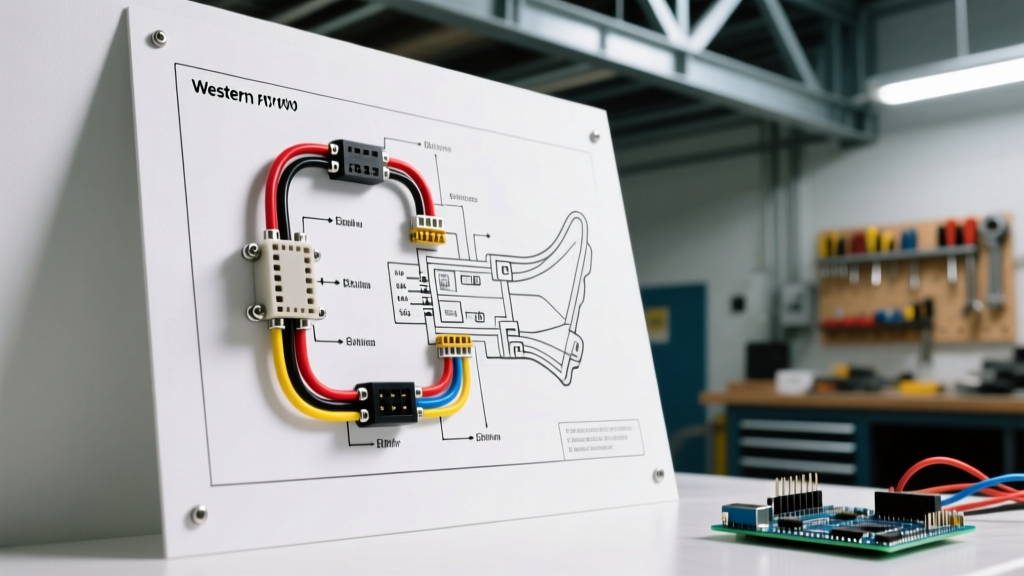
The heart of the fuel pump circuit is the Bosch-style ISO mini 4-pin relay (commonly replaced by the Standard Motor Products RY612 or Bosch 0332014150). This electromechanical switch isolates the high-amperage power circuit from the low-amperage trigger circuit. Below is the definitive pinout configuration and routing strategy for the four terminals.
High-Amperage Power Circuit (Pins 30 & 87)
- Pin 30 (Power In): Connects directly to the positive battery terminal via a primary inline fuse or circuit breaker. This wire must be routed away from exhaust headers and sharp chassis edges.
- Pin 87 (Power Out): Connects to the positive terminal of the electric fuel pump. This completes the high-current load path when the relay coil is energized.
Low-Amperage Trigger Circuit (Pins 85 & 86)
- Pin 86 (Switched 12V In): Receives a 12V signal only when the ignition is in the 'Run' or 'Start' position. In advanced setups, this signal is routed through safety cut-off switches (detailed below).
- Pin 85 (Ground): Connects to a clean, bare-metal chassis ground. Do not rely on painted surfaces or shared ground buses, as voltage drop here will prevent the relay coil from fully saturating, leading to internal arcing and relay welding.
Expert Tip: Always wire the relay coil ground (Pin 85) directly to the chassis or battery negative. Grounding the relay coil through the ECU or a low-side driver without a flyback diode can induce inductive voltage spikes that fry sensitive engine management electronics.
Wire Gauge and Fuse Sizing Matrix (12V DC Systems)
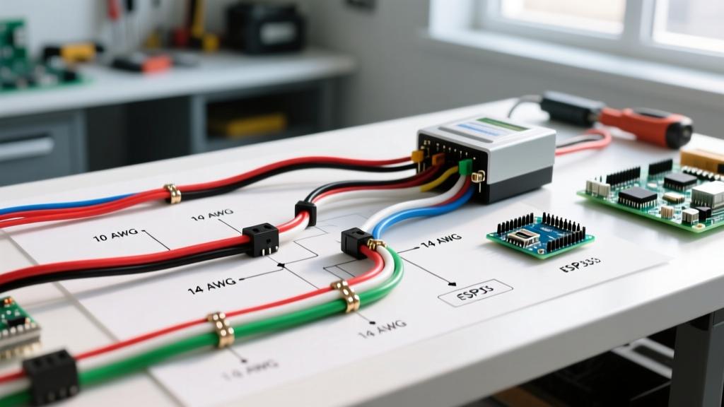
Selecting the correct wire gauge is dictated by the maximum continuous amperage draw of the pump and the total length of the wire run (positive and negative combined). Undersized wire causes voltage drop at the pump, which forces the pump motor to draw more current to maintain wattage, creating a thermal runaway scenario. The following matrix aligns common pump models with their required AWG and fuse sizing based on Blue Sea Systems and ABYC wire ampacity standards.
| Pump Model / Type | Max Draw (Amps) | Wire Run (Under 15ft) | Wire Run (15-25ft) | Inline Fuse Rating |
|---|---|---|---|---|
| OEM Replacement (e.g., Delphi FE0114) | 8A - 10A | 14 AWG | 12 AWG | 15A ATO Blade |
| Walbro GSS342 (255 LPH) | 12A - 14A | 12 AWG | 10 AWG | 20A ATO Blade |
| Aeromotive 11140 (340 LPH Stealth) | 15A - 18A | 10 AWG | 8 AWG | 25A Maxi or ANL |
| DeatschWerks DW400 (400 LPH) | 18A - 22A | 10 AWG | 8 AWG | 30A Maxi or ANL |
Note: Always use stranded, multi-strand copper wire rated for automotive environments (GXL or TXL insulation). Never use solid-core household wire (THHN/ROMEX), which will fracture under chassis vibration.
Integrating Safety Devices: Inertia and Oil Pressure Switches
A standard ignition-triggered relay leaves the fuel pump running if the engine stalls during a collision, spraying high-pressure fuel onto hot exhaust components. To meet safety standards and pass technical inspections, your wiring diagram must incorporate an automatic shut-off mechanism.
1. The Ford-Style Inertia Switch
An inertia switch (such as the Standard Motor Products FDS-5) contains a steel ball held by a magnet. Upon sudden deceleration (impact), the ball breaks the magnetic field and severs the circuit. Wire this switch in series on the Pin 86 trigger wire. If the switch trips, the relay coil loses power, instantly killing the fuel pump.
2. Oil Pressure Safety Cut-Off (Hobbs Switch)
Commonly used in carbureted race cars and marine applications, an oil pressure switch (set to close at 5-10 PSI) ensures the fuel pump only runs when the engine is actually turning and building oil pressure. This is wired in series with the ignition trigger. Warning: To allow the pump to prime the carburetor bowls before the engine cranks, a parallel bypass circuit using the starter solenoid's 'I' (Ignition) terminal is required to provide temporary 12V power during cranking.
Modern Upgrades: PWM Fuel Pump Controllers
For high-horsepower EFI builds requiring massive fuel volume at wide-open throttle (WOT) but lower volume at idle, running a 340 LPH or dual-pump setup at full 14.4V constantly will overheat the fuel and vaporize it in the rails. Modern wiring diagrams utilize a Pulse Width Modulation (PWM) controller, such as the Aeromotive 13301 Stealth.
In a PWM wiring diagram, the heavy 8-gauge power wire from the battery feeds the PWM controller's main input. The controller's output then feeds the fuel pump. The PWM controller intercepts the MAP (Manifold Absolute Pressure) or TPS (Throttle Position Sensor) signal from the ECU to dynamically adjust the voltage (via duty cycle) sent to the pump. This requires a dedicated, heavy-gauge ground wire routed directly back to the battery negative terminal to handle the high-frequency switching harmonics without creating EMI (Electromagnetic Interference) that disrupts ECU sensors.
Real-World Failure Modes & Multimeter Diagnostics
When a fuel pump fails to prime or the engine leans out under boost, the pump itself is rarely the culprit. According to AA1Car diagnostic protocols, over 60% of 'dead fuel pump' replacements are actually misdiagnosed wiring faults. Use a digital multimeter (DMM) to perform these specific tests:
Test 1: Voltage Drop on the Power Feed
- Set your DMM to DC Volts.
- Place the red probe on the battery positive terminal and the black probe on the fuel pump's positive terminal (back-probing the connector).
- Have an assistant turn the key to 'Run' to energize the pump.
- Acceptable Reading: Less than 0.2V (200mV). A reading of 0.5V or higher indicates high resistance in the positive wire, a corroded relay Pin 30/87 contact, or an undersized fuse holder.
Test 2: Voltage Drop on the Ground Circuit
- Place the red probe on the fuel pump's negative terminal and the black probe on the battery negative terminal.
- Energize the pump.
- Acceptable Reading: Less than 0.1V (100mV). High readings here mean the chassis ground is painted, rusted, or shared with too many accessories. Run a dedicated 10 AWG ground wire directly to the battery.
Test 3: Relay Coil Saturation Check
If you hear the relay 'click' but the pump doesn't run, the internal contacts may be carbon-fouled. Bypass the relay by jumping Pin 30 to Pin 87 with a heavy-gauge jumper wire. If the pump runs at full pressure, the relay is faulty, or the relay wiring pinout was misidentified during installation (e.g., swapping 87 and 87a on a 5-pin relay).
Professional Termination Standards
Soldering is generally discouraged in high-vibration, high-current automotive environments because solder wicks into the wire strands, creating a rigid point that fatigues and snaps. Instead, use an open-barrel crimp tool (such as the Delphi Weather Pack or OEM-specific crimpers) with adhesive-lined dual-wall heat shrink tubing. For connections at the fuel tank sending unit, always utilize sealed connectors like the Deutsch DT series or GM Metri-Pack to prevent fuel vapor ingress from corroding the copper strands, which acts as a resistor and starves the pump of critical voltage.