
Understanding the Wiring Diagram for One Light with Two Switches
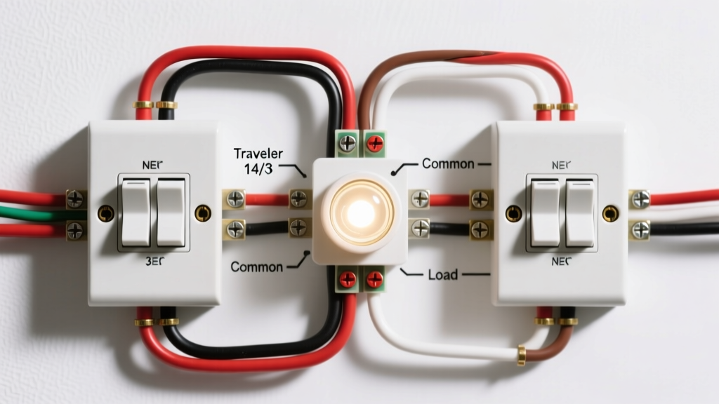
When homeowners and DIY enthusiasts search for a wiring diagram for one light with two switches, they are technically looking for a 3-way switch circuit. In electrical terminology, a standard single-pole switch is a '1-way' switch. When you introduce a second switch to control the same hardwired appliance or lighting fixture from two different locations (such as the top and bottom of a staircase, or dual entries in a large kitchen), you must upgrade to 3-way switches and utilize specialized traveler wires.
This comprehensive tutorial breaks down the physical wiring execution, the critical National Electrical Code (NEC) mandates regarding neutral wires at switch boxes, and modern smart-switch bypass techniques. Whether you are wiring a new hardwired HVAC indicator light, a workshop fixture, or a hallway sconce, precision in your wire routing is non-negotiable for safety and functionality.
CRITICAL SAFETY WARNING: Before removing any faceplate or touching bare copper, turn off the circuit breaker and verify zero voltage using a non-contact voltage tester (NCVT) and a digital multimeter. According to the Electrical Safety Foundation International (ESFI), electrocution and electrical fires remain leading hazards in residential DIY projects. Never assume a wire is dead based solely on the wall switch position.
The Anatomy of a 3-Way Circuit
Unlike a standard switch that simply breaks or completes the hot (line) wire, a 3-way switch acts as a directional gate. It routes the electrical current down one of two possible paths. To achieve this, the circuit requires specific wire configurations:
- Line (Hot): The ungrounded conductor bringing 120V power from the breaker panel (typically Black).
- Load: The wire carrying power from the final switch to the light fixture.
- Travelers: Two dedicated wires that run exclusively between the two 3-way switches, allowing current to alternate paths depending on the toggle positions (typically Red and Black within a 3-wire cable).
- Neutral: The grounded conductor completing the 120V circuit back to the panel (White).
- Ground: The safety path for fault currents (Bare copper or Green).
Essential Materials & Tool Checklist
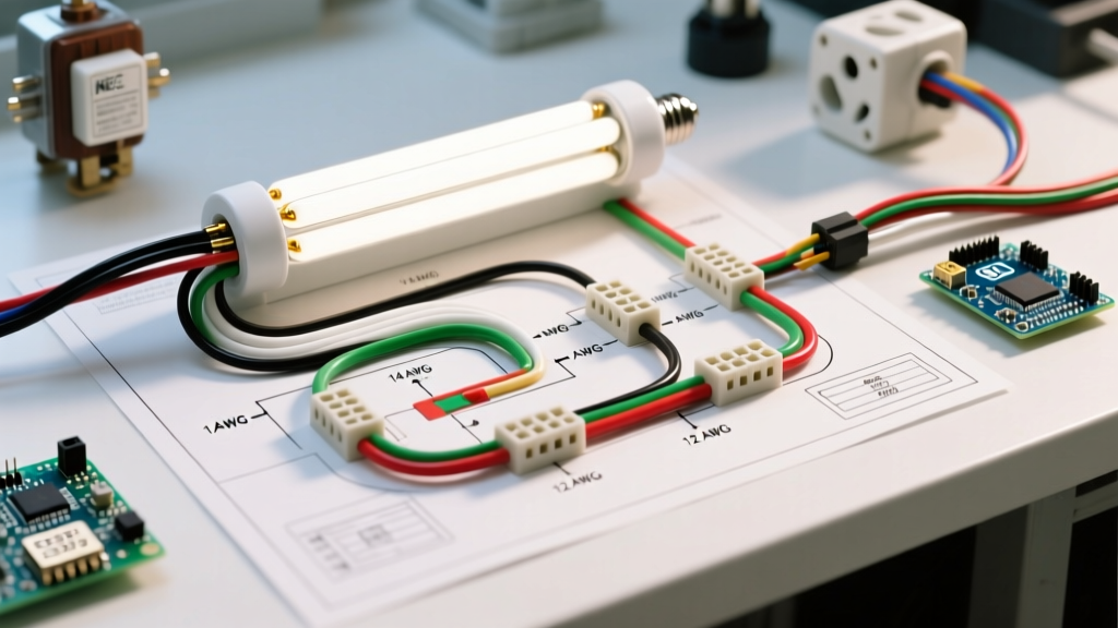
For a standard 15-amp residential lighting circuit, you must use 14 AWG copper wire. If your home's lighting circuit is tied to a 20-amp breaker, you are legally required to step up to 12 AWG wire. Below is the exact bill of materials for a standard 'Power at Switch 1' configuration.
| Item | Specification / Model | Estimated Cost (2026) |
|---|---|---|
| 3-Way Switches (x2) | Leviton Decora 5603 (15A, 120V) | $12.00 - $16.00 |
| 2-Wire Cable (14/2 NM-B) | Southwire Romex SIMpull (Panel to SW1, SW2 to Light) | $0.45 / linear ft |
| 3-Wire Cable (14/3 NM-B) | Southwire Romex SIMpull (SW1 to SW2 Travelers) | $0.65 / linear ft |
| Wire Nuts / Connectors | Ideal 341 Orange / 339 Yellow (InVisi-Lok) | $8.00 / box |
| Deep Junction Boxes | Carlon B618R (Single Gang, 18 cu in) | $2.50 each |
Step-by-Step Execution: Power at the First Switch
The most common and straightforward wiring diagram for one light with two switches assumes the main power source (from the breaker panel) enters the first switch box. Here is the exact termination sequence.
Phase 1: Routing the Cables
- Panel to Switch 1: Run 14/2 NM-B cable. This provides your Line (Black), Neutral (White), and Ground (Bare).
- Switch 1 to Switch 2: Run 14/3 NM-B cable. This provides your two Travelers (Red, Black) and a re-purposed Neutral/Traveler (White).
- Switch 2 to Light Fixture: Run 14/2 NM-B cable. This provides your Switched Load (Black), Neutral (White), and Ground (Bare).
Phase 2: Terminating Switch 1
A standard 3-way switch features three main terminal screws: one dark 'Common' screw (usually black or dark brass) and two lighter 'Traveler' screws (brass).
- Connect the Black Line wire from the panel directly to the Common (Dark) screw on Switch 1.
- Connect the Red and Black wires of the 14/3 cable to the two Traveler (Brass) screws. Order does not matter here.
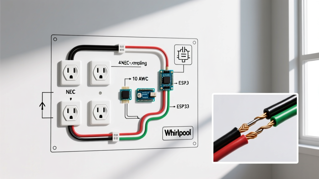
- Connect the White wire of the 14/3 cable to the White Neutral wire from the panel using a wire nut. Note: You must wrap black electrical tape around both ends of this white wire to re-identify it as a hot/current-carrying conductor per NEC Article 200.7.
- Pigtail all bare ground wires together and attach to the green ground screw and metal box.
Phase 3: Terminating Switch 2 and the Fixture
- At Switch 2, connect the re-identified White wire (now acting as your switched hot load) to the Common (Dark) screw.
- Connect the Red and Black traveler wires to the Traveler (Brass) screws.
- At the light fixture, connect the White wire from the Switch 2 cable to the fixture's Silver (Neutral) terminal. Connect the White wire from the Switch 2 cable (acting as the switched hot) to the fixture's Brass (Hot) terminal. Again, mark this white wire with black tape at the fixture box.
The 2026 NEC Neutral Mandate (Article 404.2)
One of the most frequent mistakes in older wiring diagrams for one light with two switches is the omission of a neutral wire at the switch boxes. Modern electrical codes have evolved. According to the National Fire Protection Association (NFPA) NEC Article 404.2, switch boxes controlling lighting loads must have a grounded circuit conductor (neutral) present.
This mandate exists because the modern market is dominated by smart switches, Wi-Fi relays, and motion sensors that require a constant 120V standby power circuit (Line + Neutral) to operate their internal logic boards. If you are pulling new wire in 2026, you must run 14/4 or 14/2 + 14/3 to ensure a dedicated neutral rests in every 3-way switch box, even if you are installing 'dumb' mechanical switches today. Future-proofing your rough-in saves hundreds of dollars in drywall repair and re-fishing later.
Common Failure Modes & Troubleshooting Matrix
If your circuit is behaving erratically, it is almost always due to a misidentified 'Common' terminal or a crossed traveler. Use this diagnostic matrix to isolate the fault.
| Symptom | Probable Cause | Diagnostic Fix |
|---|---|---|
| Light only works when Switch A is in the 'UP' position; Switch B does nothing. | The Line (Hot) wire is connected to a Traveler screw on Switch A instead of the Common screw. | Move the constant hot wire to the dark/black Common screw on Switch A. |
| Light toggles on/off correctly, but switches operate in reverse logic (both down = off, one up = on). | Traveler wires are swapped, or one switch is mounted upside down. | Swap the two brass traveler wires on either switch. Logic will normalize. |
| Breaker trips immediately upon toggling either switch. | Dead short. A bare ground wire is touching a brass traveler terminal, or neutral is bonded to ground at the fixture. | Inspect all wire nuts and terminal screws. Ensure no exposed copper is bridging terminals. |
| Light glows dimly or flickers when off. | Using an LED bulb on a circuit with an illuminated locator switch or induced voltage on long parallel traveler runs. | Install an Lutron LUT-MLC (Minimum Load Capacitor) across the fixture's hot and neutral. |
Modern Alternative: Smart Switch Bypass (No Travelers Required)
Retrofitting an older home where the original wiring diagram for one light with two switches lacks a neutral wire, or where the 14/3 traveler cable is damaged, used to require tearing open walls. Today, wireless smart ecosystems offer a code-compliant bypass.
Systems like the Lutron Caseta utilize a single hardwired smart switch at one location (requiring Line, Load, and Neutral). The second switch location is entirely decommissioned. The wall opening is capped, and a wireless Pico Remote is mounted over a blank faceplate. The Pico remote communicates via Lutron's proprietary Clear Connect RF protocol (which operates at 434 MHz, avoiding Wi-Fi congestion) to toggle the primary smart switch. This approach eliminates the need for traveler wires entirely and provides dimming, scheduling, and geofencing capabilities that mechanical 3-way switches cannot offer.
Final Safety and Inspection Notes
Before closing up your junction boxes, perform a 'pull test' on every wire nut to ensure mechanical integrity. The U.S. Consumer Product Safety Commission (CPSC) notes that loose neutral connections are a primary cause of residential electrical fires due to arcing faults. Ensure your wire strippers are set precisely to 14 AWG to avoid nicking the copper conductor, which creates a microscopic fracture point that can overheat under continuous load. Always label your breaker panel accurately, noting '3-Way Hallway Light' to assist future homeowners or electricians in safely isolating the circuit.