
Introduction to Pioneer Head Unit Wiring Standards
Upgrading your vehicle's audio system requires precision, patience, and a thorough understanding of electrical routing. When tackling an aftermarket installation, finding the correct wiring diagram for a Pioneer stereo is your first critical step. Whether you are installing a modern 2026 multimedia receiver like the Pioneer DMH-1776NEX or a classic MVH-S320BT digital media receiver, Pioneer strictly adheres to the EIA (Electronic Industries Alliance) color-coding standard. This universal standardization ensures that once you learn the baseline diagram, you can wire virtually any Pioneer head unit on the market.
Treating your car stereo installation with the same rigor as a hardwired home appliance tutorial means moving beyond simple 'plug-and-play' assumptions. Modern vehicles utilize complex CAN bus networks, pulse-width modulation (PWM) dimming circuits, and high-current data lines. In this comprehensive guide, we will break down the exact wiring diagram for a Pioneer stereo, detail the necessary wire gauges, and provide expert troubleshooting methodologies to ensure a flawless, noise-free installation.
The Standard EIA Color Code: Your Wiring Diagram for a Pioneer Stereo
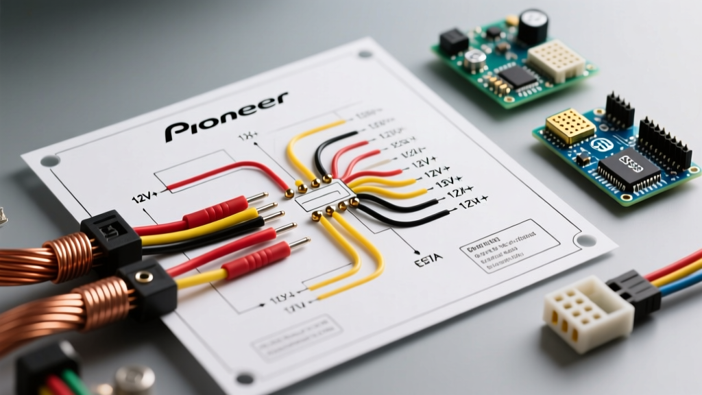
The backbone of any Pioneer installation is the primary 16-pin or 18-pin ISO/EIA power and speaker harness. Unlike factory harnesses, which vary wildly between a 2018 Ford F-150 and a 2022 Toyota Tacoma, the pigtail harness included in the box with your Pioneer stereo will always follow the EIA standard. Below is the definitive color-code matrix you must memorize or keep on your workbench.
| Wire Color | Function | Recommended Gauge | Technical Notes & Edge Cases |
|---|---|---|---|
| Yellow | Constant 12V (Battery/Memory) | 14 AWG to 16 AWG | Supplies continuous power to retain presets and clock. Must be fused within 12 inches of the battery if run direct. |
| Red | Switched 12V (Accessory/Ignition) | 16 AWG to 18 AWG | Triggers the unit to turn on. Tapping into the wrong accessory fuse can cause battery drain via parasitic draw. |
| Black | Chassis Ground | 14 AWG to 16 AWG | Must be secured to bare, unpainted metal. Poor grounding is the #1 cause of alternator whine and boot-looping. |
| Blue / White Stripe | Amplifier Turn-On / Power Antenna | 18 AWG | Outputs +12V only when the unit is on. Do not confuse with the solid Blue wire (Power Antenna only on some older models). |
| Orange / White Stripe | Illumination / Dimmer Trigger | 18 AWG | Receives a +12V signal when headlights are on. Some modern cars use PWM dimming; a PAC TR-4 module may be required. |
| White / White-Black | Front Left Speaker (+ / -) | 18 AWG | Never ground the black-striped speaker wires to the chassis. Pioneer head units use BTL (Bridge-Tied Load) amplifiers. |
| Gray / Gray-Black | Front Right Speaker (+ / -) | 18 AWG | Ensure phase alignment. Swapping + and - will result in severe bass cancellation and a hollow soundstage. |
| Green / Green-Black | Rear Left Speaker (+ / -) | 18 AWG | Verify against factory subwoofer wiring; factory amplified systems require bypassing the OEM amplifier. |
| Purple / Purple-Black | Rear Right Speaker (+ / -) | 18 AWG | Use crimp caps or heat shrink; electrical tape degrades in high-heat dashboard environments. |
Step-by-Step Appliance Wiring Tutorial: Executing the Diagram
Reading the wiring diagram for a Pioneer stereo is only half the battle. Executing the physical connections with appliance-grade reliability requires specific techniques. In 2026, the industry standard for aftermarket harness adapters (like those from Metra or Scosche) ranges from $14.99 to $29.99, depending on the vehicle's CAN bus complexity.
1. Prepping the Harness Adapter
Never splice directly into the vehicle's factory wiring. Always purchase the correct vehicle-specific adapter (e.g., Metra 70-1729 for Ford/Lincoln or Scosche GM02B for General Motors). Strip exactly 5/16th of an inch off the EIA pigtail and the adapter harness. While soldering and using 3M polyolefin heat shrink tubing provides the most permanent bond, high-quality nylon-insulated crimp butt connectors (using a ratcheting crimper like the Titan 19205) are perfectly acceptable and significantly faster.
2. Power and Ground Routing
If your vehicle's factory radio power wires are too thin to support a modern Pioneer NEX unit (which can draw up to 15 amps at peak volume), you must run a new 14 AWG power wire directly to the battery with an inline 15A ATC fuse. The Black ground wire must be terminated using a ring terminal bolted to a structural dash brace. Use a digital multimeter (such as a Fluke 117) to verify less than 0.1 ohms of resistance between your ground point and the vehicle's negative battery terminal.
3. Integrating the iDatalink Maestro Module
For vehicles requiring steering wheel control retention and OEM gauge cluster integration, the wiring diagram expands to include the iDatalink Maestro RR2. This requires plugging the proprietary 4-pin data cable into the back of the Pioneer stereo, alongside the standard EIA harness. The Maestro module intercepts the vehicle's CAN bus data and translates it into analog resistance signals that the Pioneer head unit can understand.
Expert Warning: Never connect the Pioneer 'Orange/White' illumination wire to a Maestro data harness unless explicitly instructed by the flash firmware notes. Improper illumination wiring on PWM-controlled vehicles (like modern Ram trucks or VWs) can trigger dashboard error codes or cause the stereo display to flicker violently.
Common Failure Modes and Multimeter Troubleshooting
Even when following the wiring diagram for a Pioneer stereo perfectly, edge cases arise. Here is how to diagnose the three most common installation failures using a digital multimeter.
- Stereo Loses Memory (Presets and Clock Reset): This indicates the Yellow (Constant 12V) and Red (Switched 12V) wires are swapped. Set your multimeter to DC Volts. With the car OFF, probe the Yellow wire at the harness connection. It should read ~12.6V. If it reads 0V, trace the connection back to your fuse tap or adapter harness.
- Alternator Whine (Engine Pitch Noise): This is a ground loop. It occurs when the stereo's ground and the vehicle's amplifier ground are at different electrical potentials. Check your Black wire connection. Scrape away any paint or rust under the ring terminal. If the noise persists, install a ground loop isolator on the RCA cables, though fixing the physical ground is always the superior appliance-level repair.
- Unit Fails to Turn On or Boot-Loops: Modern Pioneer touchscreens require substantial initial current to boot up. If the Red accessory wire is tapped into a low-amperage CAN bus data line instead of a true 12V accessory circuit, the voltage will sag below 10V during boot, causing a loop. Use a relay triggered by the low-amp circuit to switch full 12V power from the battery to the Red wire.
Authoritative References and Safety Standards
Adhering to established mobile electronics standards ensures your installation is safe, fire-resistant, and reliable. When interpreting any wiring diagram for a Pioneer stereo or competing brand, always cross-reference your work with industry best practices. For further reading and certification standards, consult the following authoritative resources:
- Mobile Electronics Certification Program (MECP): The MECP provides the definitive guidelines for 12V automotive electrical safety, wire gauge amperage charts, and proper crimping techniques.
- Crutchfield Learning Center: The Crutchfield Car Stereo Installation Guides offer vehicle-specific fitment data, dash kit compatibility, and factory amplifier bypass diagrams.
- Pioneer Electronics USA: The official Pioneer Car Audio Support Portal provides downloadable PDF manuals, firmware updates for NEX series units, and specific wiring schematics for proprietary backup camera harnesses.
By treating your head unit installation as a critical appliance wiring project—respecting wire gauges, securing robust grounds, and strictly following the EIA color codes—you will achieve a factory-quality fit with audiophile-grade reliability.