
Understanding the Electric Heat Sequencer Wiring Diagram
When installing or servicing commercial and residential HVAC air handlers equipped with electric strip heaters, interpreting the electric heat sequencer wiring diagram is a critical skill. Unlike standard electromagnetic contactors that pull in all high-voltage contacts simultaneously, a sequencer stages the engagement of multiple heating elements. This prevents massive inrush current spikes that would otherwise trip the main breaker or cause severe voltage dips across the building's electrical panel.
From a wire gauge and color code perspective, sequencers present a unique challenge: they bridge the gap between low-voltage control circuits (24V AC) and high-voltage line circuits (240V AC). In this comprehensive guide, we break down the exact wire gauge requirements, National Electrical Code (NEC) color coding standards, and the physical wiring flow for industry-standard sequencers like the White-Rodgers 3120 series and Honeywell L4064 models.
How Sequencers Differ from Contactors
Before pulling wire, it is vital to understand the internal mechanism. A standard contactor uses a 24V electromagnetic coil to physically pull a metal armature, closing all high-voltage contacts at the exact same millisecond. A sequencer, however, utilizes a 24V resistive heater coil that warms a bimetallic disc. As the disc heats up, it physically snaps, closing the high-voltage line contacts. This thermal expansion takes time—typically 10 to 15 seconds—creating the inherent staging delay. Furthermore, sequencers often feature an integrated fan delay switch (usually labeled 'F' or 'M') that closes slightly before or simultaneously with the heater contacts to ensure airflow is established before the strips glow red hot.
Wire Gauge Selection: 240V Line and 24V Control
Selecting the correct American Wire Gauge (AWG) is non-negotiable for fire safety and system longevity. Electric resistance heating is classified by the NEC as a continuous load because it is expected to operate for three hours or more. Therefore, the branch circuit conductors and overcurrent protection must be sized at 125% of the total heater amperage.
240V Line Voltage Wire Sizing
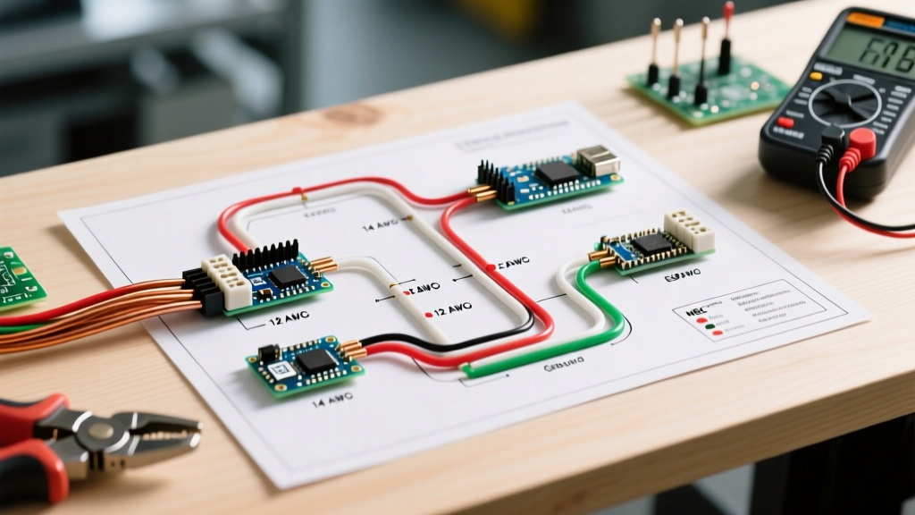
The conductors feeding the sequencer's 'H' (Heater) terminals and traveling to the heating elements must handle significant thermal loads. Below is the standard sizing matrix for 240V single-phase electric heat strips, applying the 125% NEC continuous load multiplier.
| Heater Capacity (kW) | Base Amperage (240V) | NEC 125% Sizing Amperage | Minimum Copper AWG (THHN/THWN-2) | Recommended NM-B (Romex) AWG |
|---|---|---|---|---|
| 5 kW | 20.8 A | 26.0 A | 10 AWG | 10 AWG |
| 8 kW | 33.3 A | 41.6 A | 8 AWG | 8 AWG |
| 10 kW | 41.6 A | 52.0 A | 6 AWG | 6 AWG |
| 15 kW | 62.5 A | 78.1 A | 4 AWG | 4 AWG |
| 20 kW | 83.3 A | 104.1 A | 2 AWG | 2 AWG |
Note: Always verify the manufacturer's specific terminal temperature ratings. Most modern sequencer lugs are rated for 75°C, which dictates the ampacity column you must use in NEC Table 310.16.
24V Control Circuit Wire Sizing
The low-voltage side of the sequencer connects to the thermostat or the air handler's main control board. Because the 24V coil inside a sequencer draws very little current (typically 0.1 to 0.2 Amps), heavy gauge wire is unnecessary. Standard 18 AWG multi-conductor thermostat wire is the industry standard. For runs exceeding 50 feet, stepping up to 16 AWG is recommended to prevent voltage drop, which can cause the bimetallic disc to heat too slowly or fail to snap completely, leading to arcing at the high-voltage contacts.
NEC Color Code Compliance for HVAC Sequencers
Adhering to standardized color codes ensures that any technician troubleshooting the air handler in the future can do so safely. The NFPA 70 (National Electrical Code) strictly governs line voltage coloring, while the HVAC industry has established universal conventions for 24V control wiring.
High-Voltage (240V) Color Codes
- Phase A (Line 1): Black
- Phase B (Line 2): Red (or White with black/red phasing tape)
- Ground: Bare copper or Green
- Neutral: White (Note: Pure 240V electric heat strips do not require a neutral. If the air handler utilizes 120V components like a blower motor or control board transformer, a 4-wire setup with a dedicated White neutral is required).
Low-Voltage (24V) Thermostat Wire Color Codes
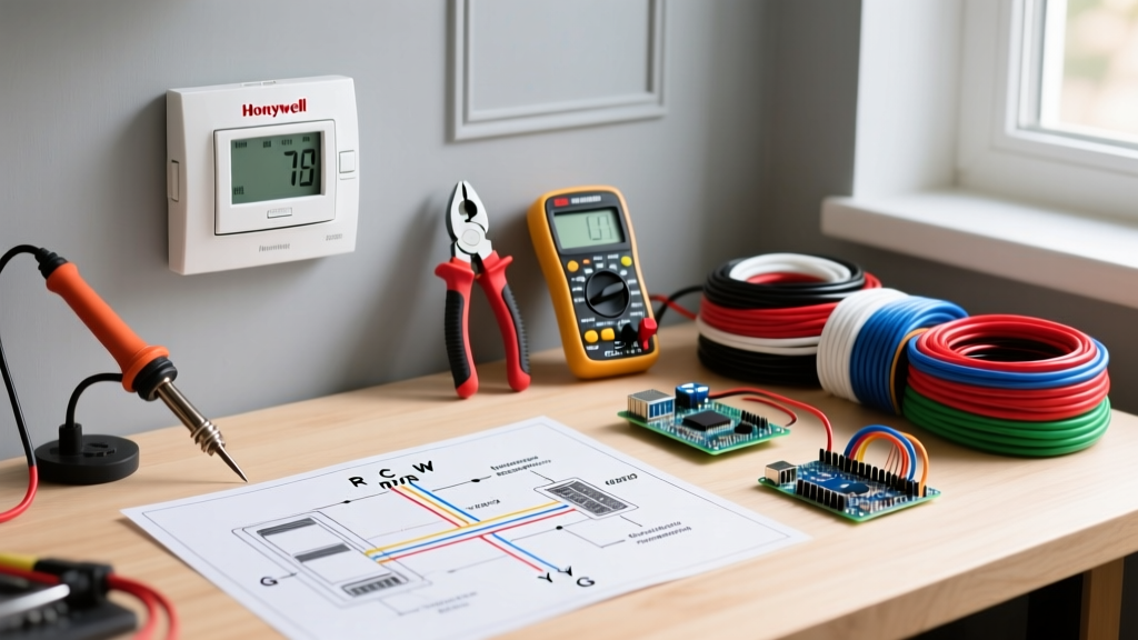
When wiring the control side of the electric heat sequencer wiring diagram, you will typically interface with the following standard thermostat wire colors:
- Red (R / Rc / Rh): 24V AC Hot from the control board transformer.
- White (W1 / W2 / Aux): First or Second stage heat call. This wire carries the 24V signal to the sequencer's coil terminal.
- Green (G): Fan relay call. (Note: If the sequencer has an internal fan switch, the 'G' wire may route through the sequencer's 'F' terminals before heading to the main blower relay).
- Blue or Black (C): 24V Common. Required to complete the circuit back to the transformer.
Step-by-Step Wiring Flow: The 3120 Series Sequencer
Let us trace the physical wiring path for a standard dual-stage setup using two sequencers (Sequencer 1 and Sequencer 2) and a 10 kW split strip heater (5 kW per stage).
- Main Power Entry: 6 AWG Black and Red wires enter the air handler from a 60A double-pole breaker. They land on the main terminal block or the first sequencer's line-in lugs.
- Daisy Chaining Line Voltage: A jumper wire (6 AWG) connects the Line-In of Sequencer 1 to the Line-In of Sequencer 2. This provides 240V to both units.
- Load Side to Elements: 10 AWG wires connect from the 'H' (Heater Out) terminal of Sequencer 1 to the first 5 kW heating element. Another 10 AWG wire connects from the 'H' terminal of Sequencer 2 to the second 5 kW element.
- Control Voltage Routing: The 24V 'W1' signal from the thermostat or control board connects to the coil terminal (often labeled '1' or 'H1') on Sequencer 1. The 'W2' or 'Aux' signal connects to the coil terminal on Sequencer 2.
- Fan Delay Integration: The 24V 'G' (Fan) signal from the thermostat enters the 'F-In' terminal on Sequencer 1. The 'F-Out' terminal then routes to the main blower motor contactor coil. This ensures the blower only receives its 24V call when the sequencer's internal thermal disc confirms the heater is engaged, preventing the elements from overheating in dead air.
Common Failure Modes and Troubleshooting
Even with perfect wire gauge selection and color coding, sequencers are mechanical devices subject to wear. According to the U.S. Department of Energy, maintaining proper electrical connections is paramount for resistance heating efficiency and safety. Here are the most common field failures:
Contacts Welding Shut
If the high-voltage wire gauge is undersized, or if the terminal lugs are not torqued to the manufacturer's specification, loose connections create immense resistance and heat. This localized heat can cause the internal high-voltage contacts to weld together. Symptom: The heating elements remain on even when the thermostat is satisfied and the 24V signal is removed. Fix: Replace the sequencer immediately and verify wire lug torque.
Coil Burnout (Open Circuit)
If the 24V control wire is damaged, or if a voltage spike occurs, the internal resistive heater coil can burn out. Symptom: The sequencer never clicks, the bimetallic disc never warms, and the specific heat stage fails to engage. Fix: Use a multimeter to check for continuity across the 24V coil terminals. An open reading (OL) confirms a dead coil requiring sequencer replacement.
Staging Overlap (Simultaneous Engagement)
If a technician incorrectly wires both sequencer coils to the same 'W1' terminal instead of splitting them across 'W1' and 'W2', both sequencers will receive the 24V signal simultaneously. While the bimetallic delays might still stagger the engagement by a few seconds, it defeats the purpose of multi-stage thermostat logic, leading to short-cycling and reduced energy efficiency.
Final Safety and Compliance Reminders
When executing any electric heat sequencer wiring diagram, always disconnect the main high-voltage breaker and lock it out (LOTO) before opening the air handler panel. Verify the absence of voltage at the sequencer line terminals using a CAT III or CAT IV multimeter. Furthermore, ensure all high-voltage splices are made inside approved junction boxes or the factory air handler enclosure, as mandated by OSHA wiring design standards. By combining precise wire gauge calculations, strict adherence to NEC color codes, and a deep understanding of thermal staging mechanics, you ensure a safe, reliable, and code-compliant electric heating installation.