
Understanding the Shunt Trip Breaker Mechanism
A shunt trip breaker is not fundamentally different from a standard thermal-magnetic circuit breaker in its primary overcurrent protection role. However, it features an integrated solenoid coil (the shunt trip accessory) that mechanically forces the breaker contacts open when an external voltage is applied. This is critical for life-safety systems, elevator recall, and commercial kitchen HVAC shutdowns mandated by NFPA 70 (NEC) and NFPA 96.
When electricians search for a reliable wiring diagram for shunt trip breaker setups, the most common point of failure is misunderstanding the control circuit's duty cycle. As of 2026, the average cost for a residential or light-commercial shunt trip breaker ranges from $65 to $95, with premium models like the Eaton CHFSHT120 or Square D HOM120SHT leading the market. Below, we provide a comprehensive, field-tested walkthrough to wire, integrate, and test these devices safely.
CRITICAL SAFETY WARNING: Shunt trip coils are designed for momentary duty only. Applying a continuous voltage signal to the C1/C2 terminals will overheat and destroy the internal coil in under 15 seconds. Your control circuit must utilize a momentary contact or a relay that drops power immediately after the breaker trips.
Core Components and Model Specifications
Before pulling wire, verify that your breaker's shunt trip voltage rating matches your control circuit's output. Sending 120VAC to a 24VDC fire alarm relay output will result in catastrophic failure.
| Manufacturer / Model | Voltage Rating | Phase / Amp Rating | Approx. 2026 Price |
|---|---|---|---|
| Eaton CHFSHT120 | 120VAC | 1-Pole / 20A | $68.00 |
| Square D HOM120SHT | 120VAC | 1-Pole / 20A | $74.00 |
| Siemens Q120SHT | 120VAC | 1-Pole / 20A | $62.00 |
| Eaton CHFSHT24 | 24VAC/VDC | 1-Pole / 20A | $85.00 |
Step-by-Step Wiring Walkthrough
Follow this sequential guide to properly wire the shunt trip accessory to your panel and external trigger source. Ensure all work complies with OSHA wiring methods and local AHJ requirements.
Step 1: Panel Preparation and Bus Stab Identification
- Turn off the main breaker and verify zero voltage on the bus bars using a CAT III or CAT IV multimeter.
- Identify a standard 1-inch wide breaker space on the panel bus. Shunt trip breakers typically occupy the same physical footprint as standard breakers, but the accessory pigtail or terminal block requires extra gutter space.
- Route your 12 AWG or 14 AWG THHN power conductors to the breaker's main lug, torquing to the manufacturer's specification (usually 12-15 in-lbs for residential panels).
Step 2: Wiring the Shunt Trip Coil (C1 and C2)
The shunt trip accessory will have two control terminals, commonly labeled C1 and C2 (or + and - for DC models). Polarity does not matter for AC coils, but strict adherence to polarity is required for DC solenoid models.
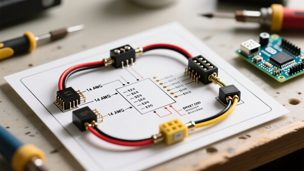
- Wire Gauge Selection: Use a minimum of 14 AWG stranded or solid copper for the control circuit. If the trigger source (like a fire alarm control panel) is located more than 100 feet away and operates on 24VDC, step up to 12 AWG to mitigate voltage drop below the coil's minimum pickup threshold (typically 70% of rated voltage).
- Termination: Strip 3/8 inch of insulation and terminate the control wires into the C1 and C2 screw terminals. Ensure no stray copper strands are bridging the terminal block to the grounded panel enclosure.
Step 3: Integrating the Trigger Source
The wiring diagram for your specific application will dictate how the control wires are routed. Below are the two most common 2026 integration scenarios:
Scenario A: Commercial Kitchen HVAC Shutdown (NFPA 96)
In commercial kitchens, the fire suppression system (e.g., Ansul) features a micro-switch that closes upon agent discharge. Wire the C1 terminal to a 120VAC dedicated circuit breaker, and wire C2 through the Ansul micro-switch back to the neutral bar. When the system fires, the switch closes, sending 120VAC to the shunt trip, instantly killing power to the exhaust fans and cooking equipment.
Scenario B: Fire Alarm Control Panel (FACP) Integration
Modern FACPs use internal relays to trigger shunt trips for elevator recall or magnetic door hold-opens. Wire the C1 and C2 terminals to the FACP's normally-open (NO) relay contacts. Ensure the FACP relay is configured for 'momentary' operation, typically programmed to pulse the relay for 2 to 5 seconds before dropping the circuit.
Step 4: The Momentary Duty Verification
Before energizing the system, verify the control logic. If you are using a Building Management System (BMS) or a smart relay to trigger the shunt trip, access the controller's programming interface. Set the output pulse duration to a maximum of 3 seconds. Failure to do this is the number one cause of shunt trip coil burnout in the field.
Step 5: Testing and Commissioning
- Restore power to the main panel and the shunt trip breaker.
- Verify the breaker is in the 'ON' position and the load is energized.
- Manually trigger the external relay or test button on the fire alarm/suppression system.
- The breaker should instantly snap to the 'TRIPPED' (center) position.
- To reset, push the breaker handle fully to the 'OFF' position until it clicks, then move it to 'ON'.
Control Wire Sizing and Voltage Drop Matrix
When utilizing 24VDC shunt trip breakers in large commercial facilities, voltage drop over long wire runs can prevent the solenoid from generating enough magnetic force to unlatch the breaker mechanism. Use the table below to size your control wires appropriately.
| Control Voltage | Distance to Trigger Source | Recommended Wire Gauge | Max Allowable Resistance |
|---|---|---|---|
| 120VAC | 0 - 250 ft | 14 AWG | 2.5 Ohms |
| 120VAC | 250 - 500 ft | 12 AWG | 1.6 Ohms |
| 24VDC | 0 - 50 ft | 14 AWG | 1.2 Ohms |
| 24VDC | 50 - 150 ft | 12 AWG | 0.8 Ohms |
| 24VDC | 150 - 300 ft | 10 AWG | 0.5 Ohms |
Troubleshooting Common Failure Modes
Even with a perfect wiring diagram for shunt trip breaker installations, field conditions can introduce faults. Consult this diagnostic matrix if your system fails to operate as intended.
| Symptom | Probable Cause | Corrective Action |
|---|---|---|
| Coil is smoking or smells burnt | Continuous voltage applied to momentary coil | Replace breaker. Reprogram BMS/FACP relay to pulse for max 3 seconds. |
| Breaker refuses to trip when signal is sent | Voltage drop below 70% threshold or blown internal thermal fuse | Measure voltage at C1/C2 during trigger event. Upgrade wire gauge or replace breaker. |
| Breaker trips, but won't reset | Mechanical latch binding or control circuit still closed | Verify trigger source has opened. Push handle firmly to OFF before moving to ON. |
| False tripping during power surges | Induced voltage on long, unshielded 24VDC control runs | Reroute control wires away from high-voltage feeders or use shielded twisted pair (STP) cable. |
Final Code Considerations for 2026
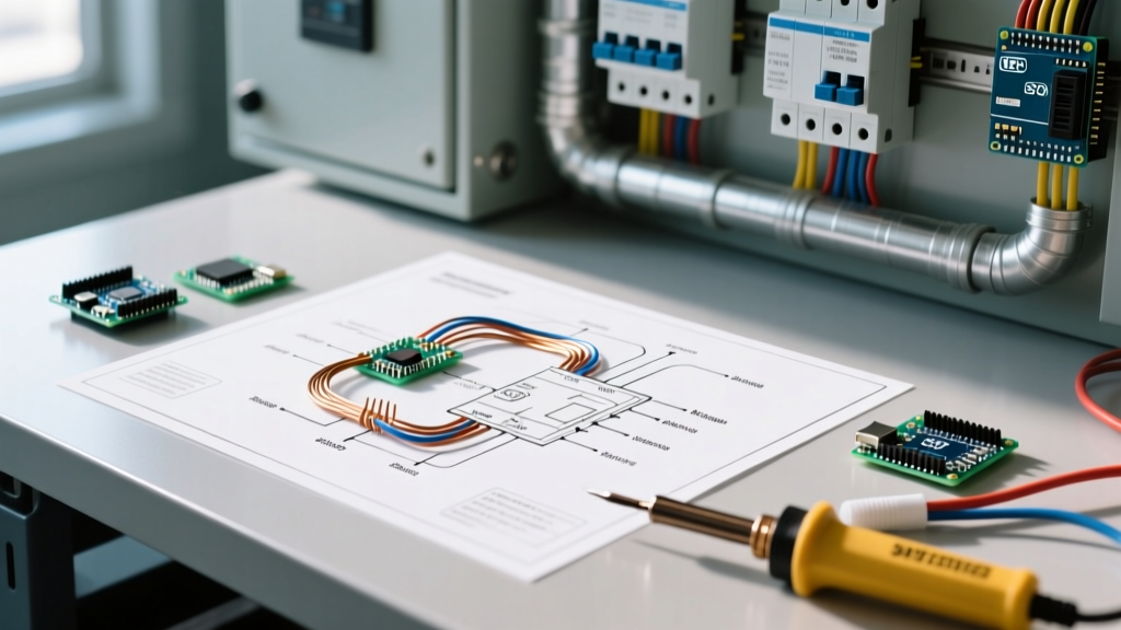
As local jurisdictions continue to adopt the latest iterations of the NEC, inspectors are heavily scrutinizing the separation of life-safety control circuits from standard power wiring. Per Eaton's technical guidelines and NEC Article 725, Class 1 and Class 2 circuit conductors must be physically separated by barriers or at least 2 inches of space within the panel gutter to prevent inductive interference and accidental contact. Always ensure your shunt trip control wires are routed neatly through dedicated panel knockouts and secured with appropriate cable clamps. By following this step-by-step wiring diagram for shunt trip breaker configurations, you ensure a safe, code-compliant, and reliable installation that will pass AHJ inspection on the first attempt.