
Bridging Low-Voltage Network & High-Voltage Panels
In modern electrical and structured wiring installations, the boundary between high-voltage breaker panels and low-voltage network enclosures is shrinking. As smart homes and commercial facilities integrate Power over Ethernet (PoE) for lighting, security, and Wi-Fi 7 access points, understanding the correct wiring diagram for RJ45 connector terminations is no longer just an IT task—it is a critical electrical skill. Improper termination near high-EMI (Electromagnetic Interference) environments like 200A or 400A main breaker panels can lead to catastrophic data loss, PoE voltage drop, and even thermal failures.
This guide approaches RJ45 termination from the perspective of structured media enclosures (like the Leviton 47603-14B or On-Q 364482-01) mounted adjacent to AC distribution panels. We will cover TIA/EIA-568 pinout standards, NEC separation requirements, and the thermal realities of 90W PoE++ (IEEE 802.3bt) in 2026 infrastructure builds.
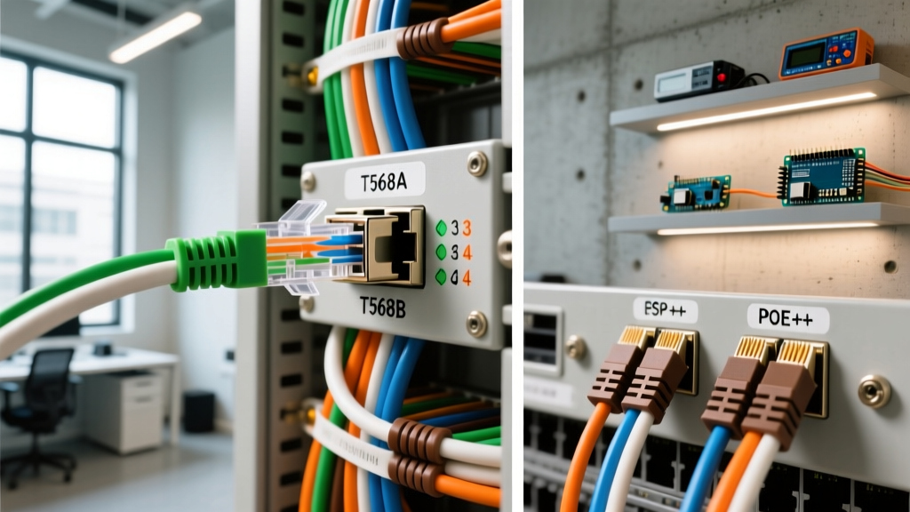
The Core Wiring Diagram for RJ45 Connector: T568A vs T568B
The ANSI/TIA-568 standard defines two primary pinout schemes for 8P8C (commonly called RJ45) connectors: T568A and T568B. While both provide identical electrical performance, T568B dominates commercial and residential contractor installations in North America, whereas T568A is often mandated in government contracts and specific legacy retrofits. When referencing a standard wiring diagram for RJ45 connector setups, maintaining consistency across the entire channel (patch panel to wall jack) is non-negotiable to avoid creating a crossover cable, which will cause link failures on non-auto-MDIX switches.
| Pin | T568B Color Code | T568A Color Code | PoE++ Function (Alt. A/B) |
|---|---|---|---|
| 1 | White/Orange | White/Green | Data / Power (+) |
| 2 | Orange | Green | Data / Power (-) |
| 3 | White/Green | White/Orange | Data / Power (+) |
| 4 | Blue | Blue | Power (+) Alt B |
| 5 | White/Blue | White/Blue | Power (-) Alt B |
| 6 | Green | Orange | Data / Power (-) |
| 7 | White/Brown | White/Brown | Power (+) Alt B |
| 8 | Brown | Brown | Power (-) Alt B |
For deeper insights into certification testing and standard compliance, refer to the Fluke Networks T568A vs T568B Guide, which details how mixed pinouts cause severe Return Loss and NEXT (Near-End Crosstalk) failures during channel certification.
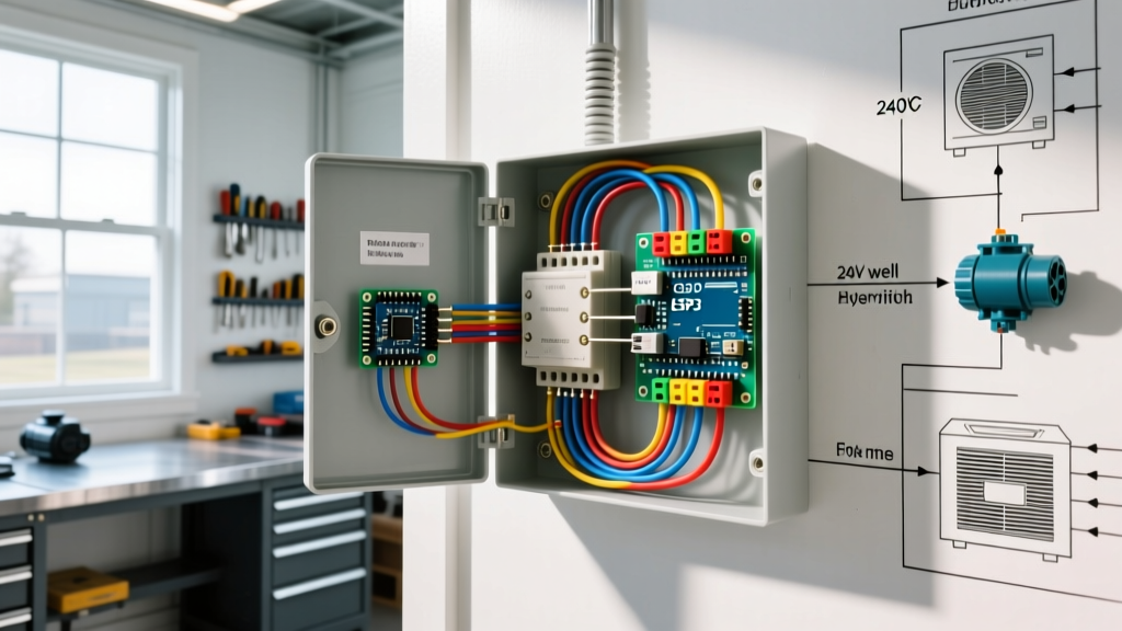
Structured Media Enclosures: Routing RJ45 Near Breaker Panels
When mounting a structured wiring panel next to a high-voltage AC breaker panel, electromagnetic interference (EMI) is the primary enemy of Cat6 and Cat6a signal integrity. The National Fire Protection Association (NFPA) NEC Article 800.133 strictly governs the separation of communications circuits from power conductors.
NEC Separation Rule: Low-voltage network cables must maintain a minimum 2-inch (50mm) separation from 120V/240V AC power cables. If crossing is unavoidable, the cables must intersect at a strict 90-degree angle. Never run Cat6a parallel to AC Romex inside the same conduit or panel knockout.
Grounding the Enclosure and Shielded RJ45 Connectors
If your run passes through high-EMI zones (e.g., near variable frequency drives, heavy HVAC contactors, or main service entrance wires), you must use shielded Cat6a (F/UTP) cable. Shielded RJ45 connectors feature a metal wrap that must be bonded to the cable's internal drain wire. Crucially, the structured media enclosure itself must be bonded to the AC panel's ground bus bar using a minimum 12 AWG or 10 AWG copper grounding wire. Failure to ground the shield turns the cable into a massive antenna, amplifying noise rather than blocking it.
Power over Ethernet (PoE++) and Panel Load Calculations
As of 2026, Wi-Fi 7 access points and PTZ security cameras routinely demand IEEE 802.3bt Type 4 PoE++, delivering up to 90W at the PSE (Power Sourcing Equipment). Pushing 90W through 23 AWG copper pairs generates significant heat. If your RJ45 connectors are bundled tightly inside a structured panel without adequate airflow, the thermal rise can melt cheap plastic connector housings and cause pin oxidation.
| PoE Standard | Max PSE Power | Cable Requirement | Panel Breaker Sizing (for PSE Switch) |
|---|---|---|---|
| 802.3af (PoE) | 15.4W | Cat5e (24 AWG) | Standard 15A/20A 120V |
| 802.3at (PoE+) | 30W | Cat6 (23 AWG) | Standard 15A/20A 120V |
| 802.3bt Type 3 | 60W | Cat6a (23 AWG) | Dedicated 20A 120V |
| 802.3bt Type 4 | 90W - 100W | Cat6a Shielded | Dedicated 20A with active cooling |
When wiring the PSE switch inside the breaker panel enclosure, ensure the AC branch circuit breaker is sized to handle the continuous load of the switch's power supply plus a 20% safety margin, per NEC Article 210.20(A). For a 24-port PoE++ switch, this often requires a dedicated 20A or even 30A circuit, depending on the simultaneous draw of the connected devices.
Step-by-Step Cat6a Termination for High-EMI Environments
To maintain the 500 MHz bandwidth of Cat6a and prevent alien crosstalk in dense panel environments, precision is mandatory. The BICSI Information Transport Systems Standards mandate strict adherence to untwist limits.
- Strip the Jacket: Use a precision stripping tool (like the Klein Tools VDV110-624) to remove exactly 1.5 inches of the outer jacket. Do not nick the internal copper conductors; a nicked wire will snap under the tension of PoE thermal expansion.
- Manage the Shield: Fold the braided shield back over the jacket. Cut the internal drain wire to length, leaving enough to wrap around the grounding tab of the shielded RJ45 plug.
- Untwist with Extreme Caution: Untwist the pairs only as far as necessary to seat them into the connector channels. Critical Limit: Never exceed 0.375 inches (9.5mm) of untwisted wire for Cat6/Cat6a. Exceeding this destroys the twisted-pair geometry, causing NEXT failures.
- Align and Insert: Flatten the conductors between your thumb and forefinger. Align them strictly to the T568B diagram. Slide them into a pass-through RJ45 connector, ensuring the jacket extends fully into the rear strain-relief crimp of the plug.
- Crimp and Trim: Use a pass-through crimper (e.g., Klein Tools VDV226-110). The tool will simultaneously crimp the pins into the copper and shear the excess wire flush with the connector face.
Common Failure Modes & Troubleshooting
- Split Pairs: The most common DIY error. This occurs when a technician maps the colors correctly but ignores the physical twist pairs (e.g., using Solid Blue and White/Orange as a pair). This results in massive crosstalk and limits link speeds to 10 Mbps, despite passing a basic continuity test. Always use a wire-mapping certifier, not just a cheap continuity beeper.
- Thermal Melt (PoE++): If using 90W PoE, standard polycarbonate RJ45 plugs can soften and deform if bundled tightly in a 24-port patch panel without active ventilation. Always specify UL-listed, high-temperature rated connectors for 802.3bt Type 4 deployments.
- Shield Ground Loops: If the cable is shielded, but the patch panel or switch chassis is not properly bonded to the building's single-point ground, the shield will carry stray AC voltage. This can destroy switch PHY chips. Always verify chassis ground with a multimeter before terminating shielded RJ45s.
Expert Tool Recommendations for 2026
Do not compromise on termination tools when working inside structured panels. The Klein Tools VDV226-110 remains the industry standard for pass-through RJ45 crimping, offering ratcheting action that ensures consistent pin depression. For verification, the Fluke Networks IntelliTone Pro 200 is essential for tracing cables inside crowded, high-noise breaker enclosures where standard tone generators fail due to EMI bleed-over. For final certification of Cat6a channels, the Fluke DSX-8000 is the only tool recognized by major cable manufacturers to validate the warranty of the installation.