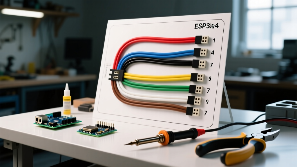

Trailer wiring is the central nervous system of your tow setup. Whether you are hauling a lightweight 5x8 utility trailer or a 30-foot enclosed car hauler, a precise wiring diagram for trailers is non-negotiable for safety and legal compliance. As of 2026, the widespread adoption of all-LED trailer lighting has reduced overall amperage draw, but it has also introduced new edge cases like hyper-flashing on older tow vehicles lacking PWM (Pulse Width Modulation) smart converters.
This guide provides a deep-dive reference into the two most common North American trailer connectors: the 4-Way Flat and the 7-Way RV Blade. We will cover exact pinouts, wire gauge matrices, and advanced troubleshooting for voltage drop and ground loop failures.
The 4-Way Flat Connector: Diagram & Pinout Reference
The 4-way flat connector is the industry standard for light-duty trailers under 3,000 lbs GVWR (Gross Vehicle Weight Rating). It handles basic lighting functions but lacks dedicated circuits for electric brakes or 12V auxiliary power. When sourcing connectors, the Hopkins 48115 or Pollak 11-721 remain the most reliable OEM-grade options on the market.
| Pin Position | Wire Color | Function | Minimum Wire Gauge (AWG) |
|---|---|---|---|
| 1 (Ground) | White | Chassis Ground Return | 16 AWG (14 AWG preferred) |
| 2 (Tail/Running) | Brown | Tail, License Plate, and Side Markers | 18 AWG (16 AWG for incandescent) |
| 3 (Left Turn/Stop) | Yellow | Left Turn Signal & Brake Light | 18 AWG |
| 4 (Right Turn/Stop) | Green | Right Turn Signal & Brake Light | 18 AWG |
Expert Insight: The Hitch Ball Ground Fallacy
A common and dangerous shortcut is relying on the hitch ball and coupler for the ground return path instead of running a dedicated white ground wire. Rust, paint, and grease create high electrical resistance. Under heavy brake-light load, this resistance causes voltage drop, leading to dim lights or complete circuit failure. Always run a dedicated 16 AWG or 14 AWG white ground wire directly from the trailer tongue to the trailer chassis using a star washer and bare metal contact.
The 7-Way RV Blade Connector: Advanced Diagram Breakdown
For trailers exceeding 3,000 lbs, campers, and equipment haulers, the 7-way RV blade connector is mandatory. This configuration is governed by the SAE J560 standard, ensuring uniformity across all heavy-duty and recreational towing applications in North America.
| Pin Position (Clockwise) | Wire Color | Function | Critical Specifications |
|---|---|---|---|
| Center | White | System Ground | Must be 12 AWG to match power circuits |
| 1 (O'Clock) | Brown | Tail & Running Lights | 16 AWG minimum for 30+ ft trailers |
| 2 (O'Clock) | Green | Right Turn & Stop | 18 AWG minimum |
| 3 (O'Clock) | Purple | Reverse Lights & Aux | Often used for reverse lockout on surge brakes |
| 4 (O'Clock) | Black | 12V Auxiliary Power | 12 AWG; 30A max via 30A inline breaker |
| 5 (O'Clock) | Blue | Electric Brakes | 12 AWG; connects to brake controller output |
| 6 (O'Clock) | Yellow | Left Turn & Stop | 18 AWG minimum |
Integrating Modern Brake Controllers
The blue wire (Pin 5) is the most critical safety circuit on a 7-way setup. It carries the modulated DC voltage from the tow vehicle's brake controller to the trailer's electric brake magnets. In 2026, proportional controllers like the Redarc Tow-Pro Liberty or the Tekonsha Prodigy P3 are the standard. These units require a flawless 12 AWG blue wire run. Using 14 AWG or 16 AWG for the brake circuit will result in a voltage drop at the trailer axle, reducing braking torque by up to 15% and causing uneven brake wear.
Wire Gauge Selection Matrix for 2026 Trailer Builds
Selecting the correct wire gauge is not just about preventing melted insulation; it is about maintaining voltage integrity over distance. The following matrix assumes a standard 12V DC system and a maximum acceptable voltage drop of 3%.
| Wire Gauge (AWG) | Max Ampacity (Chassis) | Max Length for 3% Drop @ 5A | Recommended Application |
|---|---|---|---|
| 18 AWG | 16 Amps | ~12 feet | LED Turn/Tail signals on short trailers |
| 16 AWG | 18 Amps | ~20 feet | Incandescent signals, short trailer grounds |
| 14 AWG | 32 Amps | ~35 feet | Main ground return, heavy-duty running lights |
| 12 AWG | 41 Amps | ~50 feet | Electric brakes, 12V Aux charging, main ground |
| 10 AWG | 55 Amps | ~80 feet | High-amperage winch circuits, breakaway battery feeds |
Note: As of early 2026, copper prices have stabilized around $3.80 to $4.50 per pound, making the cost difference between 14 AWG and 12 AWG automotive primary wire negligible (roughly $0.15 per foot). Always upsizing to 12 AWG for power and ground circuits is a highly cost-effective reliability upgrade.
Critical Failure Modes & Troubleshooting Edge Cases
Even with a perfect wiring diagram for trailers, real-world environments introduce variables that cause electrical failures. Here is how to diagnose the most complex edge cases:
- Hyper-Flashing with LED Upgrades: If you replaced incandescent bulbs with LEDs and your tow vehicle's turn signals flash rapidly, the vehicle's CAN-bus or BCM (Body Control Module) detects a low-current draw and assumes a blown bulb. Solution: Install a 50W/6-ohm load resistor on the yellow and green circuits, or install a dedicated PWM smart converter (like the Curt 56384) at the tow vehicle's tail light harness.
- Dim Running Lights on Long Haulers: A 30-foot enclosed trailer using 18 AWG brown wire for 12 incandescent clearance lights will suffer severe voltage drop. By the time power reaches the rear corners, voltage may drop below 10.5V. Solution: Run a 14 AWG brown "trunk" line down the center of the trailer frame, and use 18 AWG pigtails to tap into the clearance lights.
- Breakaway Switch Battery Drain: The breakaway system must be wired directly to a dedicated 12V battery (usually a 7Ah SLA or AGM battery) via a normally-open pin switch. A common wiring error is feeding the breakaway switch from the tow vehicle's 7-way black (aux) wire. If the trailer disconnects, the breakaway system attempts to pull power from a disconnected plug, rendering the brakes useless.
FMVSS 108 and DOT Compliance Standards
All trailer lighting and wiring configurations must comply with Federal Motor Vehicle Safety Standard (FMVSS) 108. This regulation dictates the photometric requirements, placement, and visibility angles for all lamps and reflective devices. According to the official FMVSS 108 documentation, trailers 80 inches or wider must feature specific identification lamps (three amber lights centered at the front, three red at the rear).
Furthermore, for commercial motor vehicles, the Federal Motor Carrier Safety Administration (FMCSA) enforces strict lighting and reflector rules under 49 CFR Part 393 Subpart D. Ensuring your wiring diagram accommodates these auxiliary marker lights—often requiring additional splices into the brown (tail) wire circuit—is essential for passing DOT inspections and avoiding hefty out-of-service fines.
Final Pre-Tow Verification Checklist
- Verify continuity from the 7-way connector ground pin to the trailer axle using a digital multimeter (should read less than 0.5 ohms).
- Test the breakaway switch by pulling the pin while the trailer is jacked up and wheels spinning freely; brakes should lock instantly.
- Check the 12V auxiliary black wire with a load tester; it should maintain at least 12.8V at the trailer plug while the tow vehicle is running.
- Apply dielectric grease (e.g., Permatex 22058) to all connector pins to prevent galvanic corrosion, especially in coastal or winter-salted environments.