
Understanding NEC Article 725 for Class 2 Doorbell Circuits
When installing a multi-zone audio notification system in a residential or commercial property, safety and code adherence are non-negotiable. A standard wiring diagram for doorbell with 2 chimes falls under the jurisdiction of the National Electrical Code (NEC) Article 725, which governs Class 1 and Class 2 remote-control, signaling, and power-limited circuits. According to the NFPA 70 (National Electrical Code), Class 2 circuits are inherently power-limited, meaning the energy source is restricted to a level that prevents fire initiation and provides acceptable protection from electric shock. However, 'low voltage' does not mean 'no rules.'
For a dual-chime setup, the primary safety concern shifts from shock hazard to thermal overload and improper routing. If an undersized transformer is forced to drive two mechanical solenoids simultaneously, the internal thermal fuse may fail, or the transformer core can overheat inside an insulated wall cavity. Furthermore, NEC 725.136 strictly mandates the separation of Class 2 wiring from Class 1 (line voltage) circuits to prevent inductive interference and accidental cross-connection.
The Anatomy of a 2-Chime Doorbell Circuit: Series vs. Parallel
The most common point of failure in multi-chime installations is misunderstanding solenoid topology. Mechanical doorbell chimes utilize electromagnetic plungers. When current flows, the plunger strikes the tone bar. How you wire two chimes to a single push-button dictates the voltage and current delivery.
The Series Method (Manufacturer Standard for Mechanical Chimes)
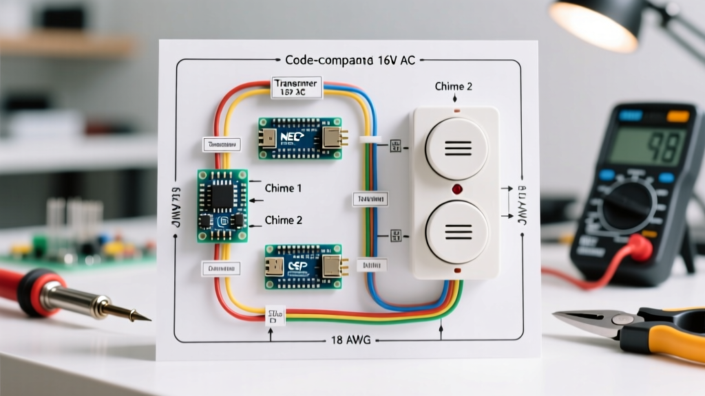
Contrary to standard household receptacle wiring, manufacturers like NuTone and Honeywell recommend wiring two mechanical chimes in series when operated by a single push-button. The current flows from the transformer, through the button, into the 'Front' terminal of Chime 1, out of the 'Trans' terminal of Chime 1, into the 'Front' terminal of Chime 2, and finally back to the transformer.
Expert Insight: Wiring in series divides the voltage. If you use a standard 16V AC, 10VA transformer (like the Honeywell AT87N), each chime will only receive roughly 8V. The solenoids will weakly hum or click, but lack the electromagnetic force to fully strike the tone bars. To compensate, you must upgrade to a 16V AC, 30VA transformer (e.g., NuTone BK125LWH) or a 24V AC, 40VA unit.
The Parallel Method (Required for Smart Doorbells & High-VA Setups)
If you are integrating a modern smart doorbell (like a Ring Pro 2 or Nest Doorbell) that requires parallel wiring to maintain its internal Wi-Fi radio, or if you are using a massive 40VA+ transformer, you wire the chimes in parallel. The button sends power to a terminal block, splitting the hot leg to the 'Front' terminal of both Chime 1 and Chime 2 simultaneously. The return wires from both 'Trans' terminals are wire-nutted together and sent back to the transformer. This requires robust wire gauges to handle the doubled inrush current without voltage drop.
Step-by-Step Wiring Diagram for Doorbell With 2 Chimes
Below is the step-by-step execution for the most robust, code-compliant setup: a 24V AC, 40VA transformer wiring two mechanical chimes in series, fully compatible with modern smart doorbell upgrades.
- Transformer Placement & Line Voltage Connection: Mount a 24V AC, 40VA transformer (such as the Honeywell AT72D1683U1006) to a standard 4x4 metal junction box. Connect the 120V AC primary wires to a dedicated or shared lighting circuit. Ensure the box has a solid ground. Per OSHA Electrical Safety Guidelines, all line-voltage terminations must be fully enclosed in grounded metal or UL-listed non-combustible enclosures.
- Running the Class 2 Cable: Use 18 AWG solid copper CL2-rated wire (e.g., Southwire 18/2 CL2). Run the cable from the transformer's secondary (24V) terminals to the push-button location. Maintain a minimum 2-inch physical separation from any 120V/240V Romex cables to comply with NEC 725.136.
- Push-Button Termination: Connect one 24V wire from the transformer to the push-button terminal. Connect the second wire from the push-button to the 'Front' terminal on Chime 1.
- Chime 1 to Chime 2 Bridge: Run a new length of 18/2 CL2 wire from the 'Trans' (Transformer) terminal on Chime 1 to the 'Front' terminal on Chime 2.
- The Return Path: Connect a wire from the 'Trans' terminal on Chime 2 back to the remaining 24V terminal on the main transformer.
- Testing & Polarity Check: While standard AC mechanical chimes are non-polarized, smart doorbell modules integrated into this circuit often require strict polarity. Use a multimeter to verify 24V AC at the push-button terminals before mounting the button.
Component Sizing Matrix: Transformers, Wire, and Distance
Voltage drop is the silent killer of multi-chime systems. As wire length increases, resistance increases, starving the solenoids of the amperage required for a physical strike. Refer to the Department of Energy NEC Overview for foundational voltage drop principles, and use the matrix below for precise sizing.
| Total Wire Run (One Way) | Wire Gauge (Solid Copper) | Transformer Output | Minimum VA Rating | Max Chimes Supported |
|---|---|---|---|---|
| Under 25 Feet | 20 AWG | 16V AC | 15 VA | 1 (Standard) |
| 25 - 50 Feet | 18 AWG | 16V AC | 30 VA | 2 (Series) |
| 50 - 100 Feet | 18 AWG | 24V AC | 40 VA | 2 (Series/Parallel) |
| 100 - 150 Feet | 16 AWG | 24V AC | 50 VA | 3+ (Parallel) |
Smart Doorbell Integration (Ring/Nest) with 2 Chimes
In 2026, the vast majority of 2-chime upgrades involve smart video doorbells. These devices leak a small amount of continuous current (typically 10-30mA) through the circuit to power their internal batteries and Wi-Fi radios, even when the button is not pressed.
The Failure Mode: In a 2-chime series circuit, this continuous micro-current can cause the mechanical solenoids to partially engage, resulting in a constant, faint buzzing sound, or it can cause the smart doorbell to constantly reboot due to insufficient voltage.
The Code-Compliant Fix: You must install a bypass accessory. If wiring in parallel, install a 25-ohm, 50-watt wirewound power resistor across the 'Front' and 'Trans' terminals of the primary chime. If the smart doorbell manufacturer provides a plug-in diode (common with Ring), install it at the push-button or the primary chime terminal to rectify the AC current and prevent the solenoid from engaging on the reverse phase.
Top 3 Code Violations & Failure Modes to Avoid
1. Mixing Class 1 and Class 2 in the Same Gang Box
A frequent DIY violation is routing the 18 AWG doorbell wire into the same single-gang box as a 120V smart light switch. Unless the box features a UL-listed physical divider, this violates NEC 725.136(A). Always use a separate, dedicated gang box for the push-button, or use a low-voltage mounting bracket (old-work ring) if the button is standalone.
2. Burying Transformers in Insulation
Transformers generate heat. While Class 2 transformers are inherently limited and rarely cause structural fires, burying a 40VA transformer under blown-in cellulose or fiberglass batt insulation prevents convective cooling. This drastically shortens the lifespan of the transformer's internal thermal fuse. Always mount the transformer to the exterior of a junction box in a clear, ventilated space, such as a basement rim joist or an attic access hatch.
3. Using Untwisted or Stranded Wire for Terminations
Doorbell chimes utilize small, clamp-style screw terminals designed for solid copper wire. Using stranded speaker wire (which is not CL2 fire-rated) often results in frayed strands causing micro-shorts, or the wire pulling out of the terminal due to vibration from the chime strikes. Always use solid-core, CL2-jacketed wire.
Frequently Asked Questions (FAQ)
Can I use a 16V 10VA transformer for two chimes?
No. While it may technically complete the circuit, a 10VA transformer lacks the amperage to drive two solenoids simultaneously. You will experience severe voltage drop, weak chime strikes, and potential thermal tripping of the transformer. Upgrade to a minimum 30VA unit.
Do I need to turn off the main breaker to wire the chimes?
The secondary side (16V-24V) of the transformer is Class 2 and safe to touch. However, you must turn off the 120V circuit breaker at the main panel when initially wiring the primary side of the transformer to the junction box. Always verify with a non-contact voltage tester before touching line-voltage wires.
Why is my second chime quieter than the first?
This is the classic symptom of voltage drop in a series circuit. The first chime consumes a portion of the voltage, leaving the second chime with insufficient power. To fix this, upgrade your wire from 20 AWG to 18 AWG or 16 AWG to reduce resistance, or switch to a 24V AC transformer to push more power through the line.