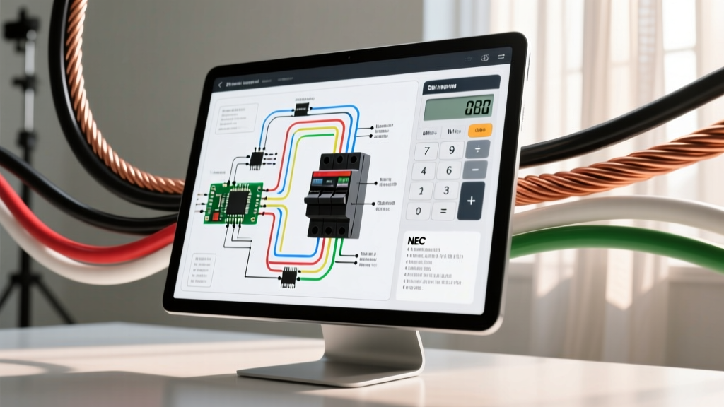

Decoding the Wiring Diagram for Two Switches (3-Way Circuits)
When electrical professionals and advanced DIYers search for a wiring diagram for two switches, they are almost always attempting to map, troubleshoot, or install a standard 3-way switch circuit. This configuration allows a single lighting load or receptacle to be controlled from two distinct physical locations, such as the top and bottom of a staircase or at opposite ends of a long hallway. While the theoretical diagram is straightforward, real-world troubleshooting often reveals a labyrinth of faded wire insulation, previous DIY hacks, and code violations that deviate sharply from the schematic.
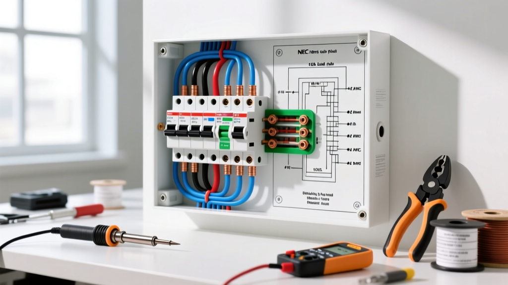
In this comprehensive guide, we will bridge the gap between the idealized wiring diagram for two switches and the physical reality inside your double-gang and single-gang junction boxes. We will cover exact multimeter testing procedures, identify dangerous edge cases like switched neutrals, and address modern National Electrical Code (NEC) requirements for smart switch upgrades.
Critical Safety Warning: Never rely solely on a non-contact voltage tester (NCVT) to confirm a de-energized circuit. Phantom voltages induced by adjacent live wires can cause false readings. Always verify the absence of voltage using a True-RMS digital multimeter (DMM) or a solenoid voltage tester (Wiggy) at the switch terminals before making physical contact. Ensure the main breaker is locked out if possible.
The Anatomy of a Standard 3-Way Diagram
To troubleshoot effectively, you must first understand the standard nomenclature used in a 3-way wiring diagram. Unlike a single-pole switch which simply breaks the hot leg, a 3-way switch acts as a transfer mechanism, routing the hot current down one of two possible paths (the travelers).
Terminal Identification and Wire Roles
- Common Terminal (Line/Load): Usually identified by a black or dark copper-colored screw. On the first switch, this connects to the incoming hot line. On the second switch, it connects to the load (the light fixture).
- Traveler Terminals: Identified by two brass-colored screws. These carry the alternating hot current between the two switches via a 3-conductor cable (typically 14/3 NM-B for 15A circuits or 12/3 NM-B for 20A circuits).
- Neutral Conductor: The white wire that bypasses the switches entirely in a traditional mechanical setup, running directly from the panel to the light fixture via a wire nut in the switch box.
- Grounding Conductor: Bare copper or green insulated wire, bonded to the green grounding screw on the switch yoke and the metal box (if applicable).
The Re-Identification Rule (NEC 200.7)
A common point of confusion when comparing a physical box to a wiring diagram for two switches is the presence of a white wire connected to a brass traveler terminal. According to NEC Article 200.7(C), when a white wire in a cable assembly is used as an ungrounded (hot) conductor or traveler, it must be permanently re-identified with black or red electrical tape or paint at both ends. If you see a white wire on a traveler terminal without tape, it is a minor code violation, but functionally it is acting as a hot traveler.
Troubleshooting Matrix: Symptoms vs. Diagram Faults
When a 3-way circuit fails, the specific behavioral symptom usually points directly to a specific wiring fault. Use this matrix to cross-reference your physical findings with your wiring diagram.
| Symptom | Probable Fault | Diagram Check & Resolution |
|---|---|---|
| Light only turns on when Switch A is in the UP position, regardless of Switch B. | Open Traveler or miswired Common on Switch B. | Check continuity on both traveler wires between boxes. Verify the load wire is on the dark Common screw of Switch B, not a brass traveler. |
| Light toggles on/off, but only if Switch A is held in a specific position. | Switch A Common terminal is wired to a Traveler. | Identify the true Line Hot using a DMM. Move the Line Hot to the dark Common screw on Switch A. |
| Breaker trips immediately when either switch is toggled. | Dead short between a Traveler and Ground, or switched neutral fault. | Inspect for pinched 14/3 NM-B cable staples. Check for illegal 'California 3-way' wiring where the neutral is being switched. |
| Light glows dimly or flickers when turned off (LED fixtures). | Induced phantom voltage on long traveler runs or missing neutral at smart switch. | Install a Lutron LUT-MLC load compensator across the fixture, or verify the smart switch neutral pigtail is bonded to the bundle, not the ground. |
Step-by-Step Multimeter Diagnostics
Throwing parts at the problem is a waste of time and money. A standard mechanical 3-way switch like the Leviton Decora 5603-2W (15A) costs under $5, while a smart dimmer like the Lutron Diva DV-5302 can exceed $60. Before replacing anything, perform this diagnostic sequence using a tool like the Fluke 117 or Klein Tools MM400.
Phase 1: Voltage Verification (Live Circuit)
- Identify the Line Hot: With the breaker ON and both switches removed (wires separated and safe), set your DMM to AC Voltage. Place the black probe on the bare ground bundle and the red probe on each wire in Box 1. The wire that reads ~120V (typically between 114V and 126V) is your Line Hot. Mark it with black tape.
- Check the Load Leg: In Box 2, test the wires against ground. You should read 0V on all wires unless the fixture is somehow backfeeding (rare). The wire that leads to the fixture is your Load. Mark it.
- Verify Traveler Continuity: Turn the breaker OFF. Set the DMM to Continuity (the diode/beep setting). Place probes on the red wire in Box 1 and the red wire in Box 2. You should hear a beep (near 0.0 ohms). Repeat for the black traveler. If one reads 'OL' (Open Line), you have a broken wire inside the wall or a failed wire nut connection in an intermediate junction box.
Phase 2: Switch Mechanism Testing (De-energized)
Sometimes the wiring is perfect, but the internal toggle mechanism of the switch has carbon-tracked or failed. Set your DMM to continuity. Place one probe on the Common (dark) screw and the other on Traveler 1. Flip the toggle. The meter should alternate between 0.0 ohms and OL. Move the probe to Traveler 2 and repeat. If the switch fails to alternate cleanly, the internal spring or contactor is shot. Replace the switch.
Modern Complications: Smart Switches and the NEC Neutral Requirement
The most common reason DIYers pull up a wiring diagram for two switches in 2026 is to upgrade to smart lighting or advanced LED dimmers. This introduces a massive complication: the neutral wire.
Traditional mechanical 3-way switches do not require a neutral wire in the switch box; they only break the hot leg. However, smart switches (like the Lutron Caseta or Leviton Decora Smart Wi-Fi series) contain internal radios, microcontrollers, and LED indicators that require a continuous 120V circuit to operate. This means the smart switch needs both a Line Hot and a Neutral to power its internal brain, while simultaneously switching the Load.
NEC Article 404.2(C) and the Missing Neutral
Recognizing this exact issue, the NFPA updated NEC Article 404.2(C) to mandate that a neutral conductor must be present at all switch locations controlling lighting loads. If you are working in a home built before 2011, your switch boxes likely lack a neutral bundle.
- The Solution: If a neutral is not present in the box, you cannot legally or safely install a standard Wi-Fi/Z-Wave smart switch. You must either pull a new 14/3 or 12/3 cable from the fixture to the switch box to bring the neutral down, or use a system like Lutron Caseta Clear Connect, which utilizes a Pico remote and a module installed at the fixture canopy, bypassing the need for a neutral at the wall switch entirely.
- The Danger: Never bootleg a neutral by connecting the switch’s neutral pigtail to the bare copper ground wire. This sends return current down the equipment grounding conductor, creating a shock hazard, causing electromagnetic interference (EMI), and violating fundamental safety codes.
Edge Case: The Illegal 'California 3-Way'
When troubleshooting older homes, you may encounter a wiring setup that completely defies standard diagrams. Known colloquially as the 'California 3-Way' or 'Coast 3-Way', this setup was historically used to save wire on long runs by switching the neutral instead of the hot leg, or by using a 4-wire setup that leaves the fixture socket constantly energized with 120V even when the light is off.
If your voltage tester indicates that the metal shell of the light fixture socket is hot when the switches are in the 'off' position, you have a switched neutral or a California 3-way. This is a severe shock hazard, particularly when changing lightbulbs. The only permanent fix is to completely rewire the circuit to ensure the hot leg is switched and the neutral is bonded directly to the fixture's silver terminal.
Summary and Final Verification
Troubleshooting a 3-way circuit requires a methodical approach. By comparing the physical wires in your junction boxes against a standard wiring diagram for two switches, identifying the Line, Load, and Travelers with a True-RMS multimeter, and respecting modern NEC neutral requirements, you can resolve almost any fault. Always torque terminal screws to the manufacturer's specifications (usually around 12 to 14 in-lbs for standard 15A residential switches) to prevent arcing and thermal degradation over time.