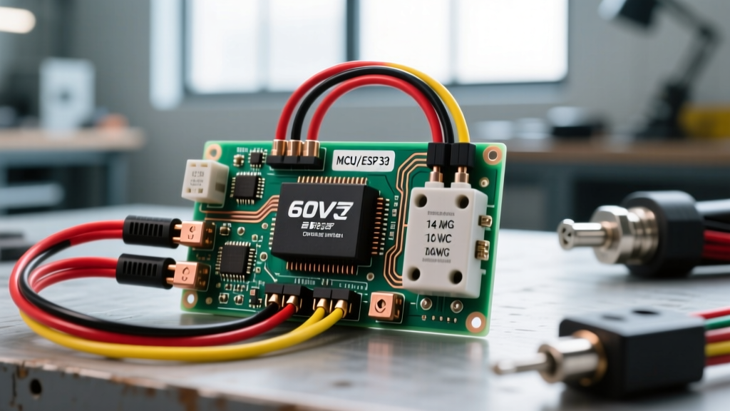

The Micro-Panel Concept in High-Power PEVs
When upgrading or building a high-performance personal electric vehicle (PEV), treating the power distribution system like a residential electrical panel is critical for safety and reliability. A 60V nominal lithium-ion battery pack (which peaks at 71.4V when fully charged) can deliver devastating amounts of current. In a high-performance setup utilizing a controller like the Votol EM-100 or Sabvoton 72V, continuous battery currents can exceed 80A, with phase currents spiking past 150A during hard acceleration.
Without a properly designed 'micro-panel'—comprising a main DC overcurrent protection device (OCPD), a heavy-duty contactor, and an anti-spark precharge circuit—you risk catastrophic failure modes. These include welded contactors, vaporized XT90 connectors, or thermal runaway in the battery pack. This guide provides a comprehensive 60v electric scooter controller wiring diagram perspective, focusing heavily on panel architecture, DC breaker sizing, and fail-safe integration.
Core Components of the 60V Distribution Panel
Before cutting any wire, you must source components rated specifically for high-voltage DC applications. AC breakers will fail to extinguish DC arcs, leading to internal fires. Below is the 2026 market breakdown for a robust 60V/72V peak distribution setup.
| Component | Recommended Model / Spec | Estimated Cost (2026) | Function in Micro-Panel |
|---|---|---|---|
| Controller | Votol EM-100 (84V Max, 150A Phase) | $185.00 | Motor commutation and logic control |
| Main DC Breaker | 2-Pole 100A DC MCB (1000VDC, 10kA AIC) | $28.00 | Main OCPD and physical disconnect |
| Contactor | Trombetta 12V Coil, 100A Cont. | $45.00 | Key-switched high-current relay |
| Main Power Wire | 8 AWG Silicone (600V, 200°C) | $35.00 / 10ft | Low-resistance main bus routing |
| Connectors | Amass QS8 (Anti-Spark) | $14.00 / pair | Battery-to-Panel physical connection |
Step-by-Step: 60v Electric Scooter Controller Wiring Diagram
The following sequence outlines the physical wiring flow from the battery pack to the controller, integrating the necessary protective layers. Always use a dedicated crimping tool (such as the Knipex 97 53 14) for all terminal lugs, and seal them with 3:1 adhesive-lined heat shrink to prevent moisture ingress and oxidation.
1. Battery to Main DC Breaker (The Main Lug)
Route the main positive (B+) and negative (B-) from your battery's QS8 connector directly to the input terminals of the 2-Pole 100A DC MCB. Do not place any switches or fuses between the battery output and the main breaker. The breaker must be the first point of protection. Use 8 AWG wire, keeping the run as short as possible (under 12 inches) to minimize voltage drop and inductance.
2. Breaker to Contactor (The Switched Bus)
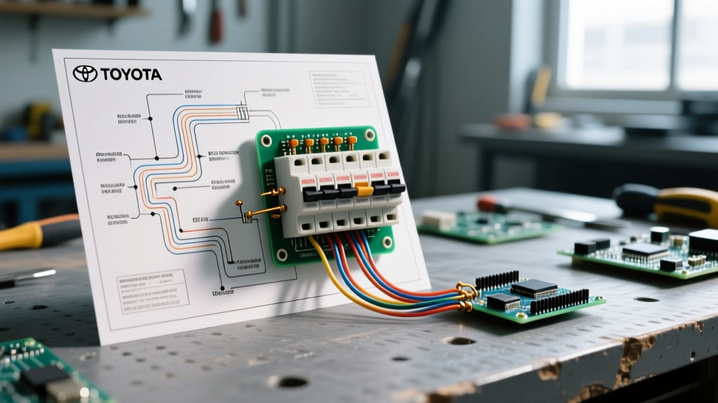
From the output side of the DC MCB, route the B+ to the high-current input terminal of the Trombetta contactor. The B- line will bypass the contactor and run directly to the controller's main negative terminal (B-). In high-power PEVs, we typically only switch the positive leg via the contactor to reduce complexity and points of failure, provided the main breaker disconnects both poles for emergency isolation.
3. Contactor to Controller B+
Connect the output terminal of the contactor to the main B+ input on the Votol EM-100 controller. Ensure the terminal is torqued to the manufacturer's specification (usually around 4-5 Nm for M6 bolts on the controller bus bars). Loose connections here will cause localized heating, melting the controller casing under 80A continuous loads.
4. The Ignition and Precharge Circuit (Crucial Step)
This is where most DIY builds fail. If you close a 100A contactor directly onto a controller with thousands of microfarads of empty input capacitance, the instantaneous inrush current can exceed 1,000A. This will weld the contactor contacts shut and blow the controller's input capacitors. According to Battery University's guide on lithium-ion protection, managing inrush and discharge spikes is vital for preserving both the battery chemistry and downstream electronics.
- Precharge Resistor: Wire a 470-ohm, 50W ceramic resistor in parallel with the main contactor terminals.
- Ignition Signal: Run a 16 AWG wire from the contactor's output (controller side) to the controller's 'Ignition' or 'Lock' pin. When you turn the key, the ignition pin wakes the controller, drawing a tiny current through the precharge resistor to slowly fill the capacitors. Once the voltage equalizes, the main contactor engages (often triggered by a secondary logic relay or the controller's internal precharge logic).
Expert Panel Tip: Never rely solely on an anti-spark connector (like the Amass XT90-S) as your primary precharge method in a 60V/150A system. The internal resistor in those connectors is designed for 14S (52V) systems and will quickly burn out under the 71.4V peak of a 17S 60V pack. Always use a dedicated external precharge circuit.
Sizing DC Breakers: Battery Current vs. Phase Current
A common point of confusion when interpreting a 60v electric scooter controller wiring diagram is the difference between battery current and phase current. The U.S. Department of Energy's Alternative Fuels Data Center notes that EV powertrains utilize complex inverter logic to multiply torque at the wheels, which dictates how we size our OCPDs.
The Sizing Formula
Your main DC breaker must be sized based on the Battery Current Limit set in the controller software, not the Phase Current.
- Phase Current (e.g., 150A): This is the current flowing between the controller and the motor windings. It is largely reactive and does not pass through the main DC breaker from the battery.
- Battery Current (e.g., 80A): This is the actual continuous DC amperage drawn from the battery pack through the main wiring harness.
If your Votol EM-100 is programmed for an 80A battery limit, a 100A DC MCB is the correct choice. This provides a 20% safety margin for transient spikes while ensuring the breaker trips before the 8 AWG silicone wire (rated for ~100A continuous in free air) reaches its thermal limit.
Panel Layout and EMI Shielding
When physically mounting these components inside the scooter deck, treat the layout like a sensitive communications panel. High-current DC switching generates massive Electromagnetic Interference (EMI).
- Physical Separation: Keep the main B+/B- power cables at least 2 inches away from the Hall sensor cables, throttle signal wires, and USB charging lines.
- Twisted Pairs: If you must run phase wires near signal wires, ensure the phase wires are tightly twisted together to cancel out their magnetic fields.
- Grounding the Shield: If your motor uses shielded phase cables, ground the shield only at the controller end to prevent ground loops.
Common Failure Modes and Troubleshooting
Even with a perfect wiring diagram, real-world edge cases occur. Here is how to diagnose the most common 'panel' failures in 60V builds.
Nuisance Tripping vs. True Short Circuit
If your 100A DC breaker trips immediately upon hard acceleration, check the trip curve. Standard Type B or C AC breakers adapted for DC use will trip on the inductive kickback of the motor startup. You must use a Type D or specifically rated DC MCB designed to tolerate high magnetic inrush. Furthermore, consult the NFPA 70 National Electrical Code (NEC) guidelines regarding continuous vs. non-continuous loads; motor controllers are highly dynamic and require OCPDs that can handle momentary 125% overloads without thermal memory tripping.
The BMS Cutoff Illusion
If the scooter dies under heavy load but the DC breaker remains fully engaged (ON), the fault is rarely the wiring. It is almost always the Battery Management System (BMS). If your BMS is rated for 60A continuous but your controller pulls 80A, the BMS will execute a hard-cut to protect the cells. This leaves the breaker untripped but the scooter completely dead. Rule of thumb: Your BMS continuous discharge rating must always exceed your controller's programmed battery current limit by at least 15%.
Contactor Chatter
A rapid clicking sound from the Trombetta contactor indicates a voltage drop in the 12V coil circuit. The coil requires a solid 12V source, preferably stepped down from the main pack via an isolated DC-DC converter (like a Mean Well SD-25-12). If you tap the coil power from a weak auxiliary 12V battery that is sagging under load, the contactor will chatter, arc internally, and eventually weld shut.
Final Safety Verification
Before applying main power, use a digital multimeter to verify continuity. Ensure there is no continuity between the main B+ and the chassis (if using a metal deck). Once verified, flip the main DC breaker. You should hear a faint 'click' from the precharge circuit equalizing the voltage, followed by the solid 'clack' of the main contactor engaging. Monitor the controller temperature via Bluetooth telemetry during your first test ride; if the power terminals exceed 60°C (140°F), re-crimp your lugs and verify your torque specs.