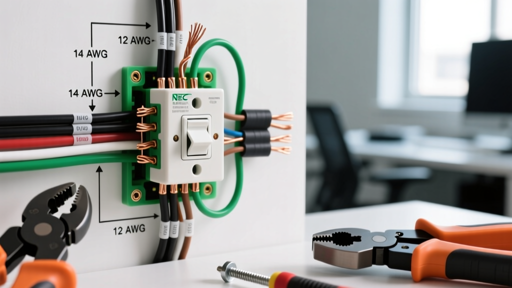

Decoding the Wiring Diagram for Switch Configurations
When interpreting a wiring diagram for switch installations, the schematic is only half the battle. The physical execution relies entirely on selecting the correct wire gauge (AWG) and strictly adhering to National Electrical Code (NEC) color mandates. A misinterpreted diagram or an undersized conductor doesn't just trip breakers; it creates high-resistance fault points that lead to thermal degradation and arc faults. In 2026, with the proliferation of smart home ecosystems and continuous LED loads, understanding the intersection of switch topology, conductor ampacity, and color-coding is critical for both DIYers and licensed electricians.
This reference guide bridges the gap between abstract schematics and physical wire selection, focusing on single-pole, 3-way, and 4-way switch loops while integrating the latest NEC compliance standards.
NEC Conductor Color Code Matrix for Switch Loops
The NEC (specifically Articles 200, 250, and 310) strictly dictates conductor identification. When executing a wiring diagram for switch circuits, assuming a wire's function by its position rather than its insulation color is a primary cause of miswiring. Below is the definitive color-code matrix for standard 120V/240V residential switch loops.
| Conductor Function | NEC Mandated Color | Switch Terminal | Code Exceptions & Field Notes |
|---|---|---|---|
| Equipment Ground | Bare Copper or Green | Green Ground Screw | Must be continuous; never switched. (NEC 250.148) |
| Neutral (Grounded) | White or Gray | Not terminated on standard toggle | Required in switch box for smart switches (NEC 404.2(C)). |
| Line / Hot (Ungrounded) | Black, Red, or Blue | Brass 'Line' Screw | Black is standard for 120V single-pole line voltage. |
| Load (Switched Hot) | Black or Red | Brass 'Load' Screw | Feeds the fixture. Must be re-identified if using white cable. |
| Travelers (3-Way/4-Way) | Red, Black, or Blue | Brass Traveler Screws | Colors must match at both ends of the 3-wire cable run. |
The 'Re-Identified White' Edge Case
One of the most common deviations in older wiring diagrams for switch loops is the use of a 2-wire cable (Black, White, Bare) dropped from a ceiling fixture to a wall switch. In this scenario, the white wire is utilized as the switched hot returning to the fixture. Per NEC 310.12(A), any white or gray conductor used as an ungrounded (hot) conductor must be permanently re-identified at both termination points using black or red electrical tape, or permanent marker. Failing to re-identify this wire creates a severe shock hazard for future technicians who assume the white wire is a neutral.
Wire Gauge Selection and Ampacity Limits
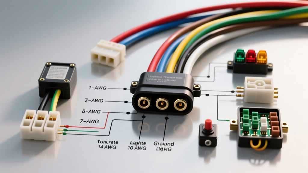
A wiring diagram for switch setups will rarely specify the exact American Wire Gauge (AWG) to use; it assumes the installer knows the circuit's overcurrent protection device (OCPD) rating. Wire gauge must be matched to the circuit breaker, not the switch itself. While a standard Leviton 5603 single-pole switch is rated for 15 Amps, it can safely be installed on a 20-Amp circuit provided the circuit wiring is 12 AWG.
- 14 AWG Copper (THHN/THWN-2): Rated for 15 Amps. Maximum breaker size 15A. Resistance is approximately 2.525 ohms per 1,000 feet. Ideal for dedicated lighting circuits where voltage drop is minimal.
- 12 AWG Copper (THHN/THWN-2): Rated for 20 Amps. Maximum breaker size 20A. Resistance is approximately 1.588 ohms per 1,000 feet. Required for kitchen, bathroom, and outdoor receptacle circuits that may also feed a switch loop.
- 10 AWG Copper: Rated for 30 Amps. Rarely used for standard wall switches, but necessary for heavy-duty appliance disconnect switches (e.g., 240V water heater cutoffs).
Voltage Drop in Long Switch Runs
When a wiring diagram for switch configurations involves long runs—such as a 3-way switch setup controlling a detached garage light—voltage drop becomes a critical factor. The NEC recommends a maximum 3% voltage drop on branch circuits. If your 3-way traveler run exceeds 75 feet on a 15A circuit using 14 AWG wire, you must upsize to 12 AWG to prevent dimming and premature failure of LED drivers. Always calculate voltage drop based on the one-way distance of the cable, not the total loop length.
The NEC 404.2(C) Neutral Mandate for Smart Switches
If you are updating a legacy wiring diagram for switch upgrades to accommodate smart home technology (like the Lutron Caseta or Enbrighten Z-Wave toggles), you will encounter the neutral wire requirement. Modern smart switches contain internal relays, Wi-Fi radios, and microprocessors that require a continuous 120V standby circuit. This necessitates both a Line (Hot) and a Neutral conductor present in the switch box.
Code Alert: Since the 2011 NEC cycle, and strictly enforced in 2023/2026 adoptions, NEC 404.2(C) mandates that a neutral (grounded) conductor must be provided at the switch box. If you are pulling new cable for a switch loop, always use 3-wire cable (Black, Red, White, Bare) even for a basic single-pole switch, capping the unused red or white wire with a Wago 221-412 lever nut for future-proofing.
Termination Standards and Torque Specifications
The physical termination of the wires depicted in your wiring diagram for switch layouts is where most field failures occur. Relying on 'hand-tight' feels is an outdated practice. NEC 110.14(D) requires that terminations be torqued to the manufacturer's specifications.
For standard 15A and 20A residential switches (such as the Leviton Decora line or Eaton wiring devices), the manufacturer specifies a terminal screw torque of 12 to 14 inch-pounds. Using a calibrated torque screwdriver (like the CDI 401SM) ensures the conductor is compressed sufficiently to prevent micro-arcing without snapping the brass screw head or deforming the copper strand.
Wire Stripping Precision
Use the built-in strip gauge on the back of the switch yoke. Typically, this requires stripping exactly 1/2 inch to 5/8 inch of insulation.
- Under-stripping: Leaves insulation trapped under the terminal screw washer, creating a high-resistance connection that will melt under load.
- Over-stripping: Exposes bare copper outside the terminal box, creating a short-circuit hazard if the bare wire touches the metal wall box or the ground wire.
Common Failure Modes in Switch Wiring
1. The 'Backstab' Push-In Connector Trap
Many modern switches feature push-in (backstab) terminals for quick installation. While UL-listed, these rely on a single spring-steel contact point gripping the 14 AWG wire. Under continuous thermal cycling (heating and cooling as loads are switched), the spring steel loses tension, leading to a loose connection, arcing, and eventual melt-down. Actionable advice: Always use the side-wiring terminal screws. Form a 'J-hook' with the stripped wire using needle-nose pliers, loop it clockwise around the screw, and tighten. This ensures the screw pulls the wire tighter as it turns.
2. Shared Neutral Multi-Wire Branch Circuits (MWBC)
When interpreting a wiring diagram for switch setups in commercial or high-end residential builds, you may encounter a 3-wire cable (Black, Red, White, Bare) feeding two separate single-pole switches. This is a Multi-Wire Branch Circuit. The white wire is a shared neutral carrying only the unbalanced load.
Critical Safety Rule: Per NEC 210.4(B), the two hot wires (Black and Red) MUST be on opposite phases (240V between them) and must be disconnected simultaneously using a double-pole breaker or handle ties. If an electrician replaces the switches and turns off only one breaker, the shared neutral remains energized by the second phase, posing a lethal shock hazard.
Reference Resources and Further Reading
To ensure your switch wiring projects remain compliant and safe, always consult the most current code cycles and safety standards. The following authoritative resources provide the foundational data for wire ampacity and switch installation protocols:
- National Fire Protection Association (NFPA) - National Electrical Code (NEC): The definitive source for Articles 200, 310, and 404 governing conductor identification, ampacity, and switch installation requirements.
- Occupational Safety and Health Administration (OSHA) - Electrical Safety Standards: Essential guidelines for lockout/tagout (LOTO) procedures and safe work practices when terminating live switch panels.
By treating the wiring diagram for switch circuits not just as a visual map, but as a strict mandate for gauge sizing, color coding, and torque precision, you ensure a resilient, code-compliant electrical system that will safely power modern loads for decades.